My bad, wrong link in the buffer, the one that I wanted to show wasThat's a 5v unit. You mean 15v dual rail like this?
DKE10A-15: Mean Well : POWER SUPPLY ENCAPSULATED DC-DC 2 OUTPUT 15 VOLT-15 VOLT 0.333A/-0.333A 10W 5-PIN : Power Supplies & Wall Adapters
60mV ripple will require more filtering with CLC or something. Also 18v max input can that handle 19v brick?
Meanwell DKA15B-15 which provides more juice that the above. The input range is 18-36 VDC, and the output is 0.5A per rail. I also ordered the DKE10A-12 as I have quite a few 12VDC and 19VDC working power brick from dead laptops.
Take a look at http://www.diyaudio.com/forums/head...eadphone-amp-linear-audio-80.html#post4029581 on using some bypass caps for the noise and local decoupling cap which Prasi added to the pcb.
That's a 5v unit. You mean 15v dual rail like this?
DKE10A-15: Mean Well : POWER SUPPLY ENCAPSULATED DC-DC 2 OUTPUT 15 VOLT-15 VOLT 0.333A/-0.333A 10W 5-PIN : Power Supplies & Wall Adapters
60mV ripple will require more filtering with CLC or something. Also 18v max input can that handle 19v brick?
The 60mV (max) is quoted at 20MHz according to the spec sheets so maybe it will not require more filtering.
My bad, wrong link in the buffer, the one that I wanted to show was
Meanwell DKA15B-15 which provides more juice that the above. The input range is 18-36 VDC, and the output is 0.5A per rail. I also ordered the DKE10A-12 as I have quite a few 12VDC and 19VDC working power brick from dead laptops.
Take a look at http://www.diyaudio.com/forums/head...eadphone-amp-linear-audio-80.html#post4029581 on using some bypass caps for the noise and local decoupling cap which Prasi added to the pcb.
No problem about the wrong link, we understood what you meant.
With the DKA15B-15, a single one would be sufficient for a stereo Head Amp

Thanks,
Eric
My bad, wrong link in the buffer, the one that I wanted to show was
Meanwell DKA15B-15 which provides more juice that the above. The input range is 18-36 VDC, and the output is 0.5A per rail. I also ordered the DKE10A-12 as I have quite a few 12VDC and 19VDC working power brick from dead laptops.
Take a look at http://www.diyaudio.com/forums/head...eadphone-amp-linear-audio-80.html#post4029581 on using some bypass caps for the noise and local decoupling cap which Prasi added to the pcb.
Thanks and for that link - certainly a good price compared to how much it will cost to make it with linear supplies.
I have built a few MC for my preamp, DAC, and CD transport projects. Therefore, I pretty much have a MC ready to use this for the JF5HA. I never tried this kind of convertor, and since I plan to build a Marsh HA next. I figured I should give it a try. It will work for both MHA and JF5HA anyway. IMHO, that's the beauty of DIY - go figure ourselves
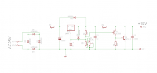
That's not the schematic I posted or built.
My schematic is somewehere in the F5 thread and uses D44H11/D45H11.
Yes, I know that your sch uses D44H11 and D45H11, Also BC850/ BC860. Thats the reason why I asked in the post "can someone comment on component chioce of BC560 and TIP31".
For that matter, can you suggest any other replacements for D44/45 pair or BC pair.
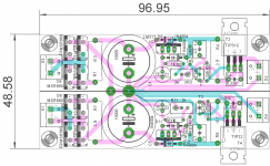
here is a first draft of the layout. needs a bit of fine tuning for sure.
reg
Prasi
Attachments
Last edited:
I think TIP 41/42 are easier to find and allow more current. You may want to mount the LM317/337 on same heatsink or allow more space for local heatsink. All the current passes through it I think. With 100mA to 150mA bias, the heating is only a watt at most so a small local heatsink is probably fine. If it is mounted inside an aluminum case, then direct mounting to case wall is nice way to sink heat too. I find no need for fins on case.
Have you run a sim of the modified Stixx shunt regulated PSU yet? I think the Juma Easy Peasy cap multiplier gives better ripple control. Just use it following the LM317/337 adjusted for 4v above 15v as there is 4v drop. I have simulated it with IRF610/9610 and it works well and is simpler to make.
Have you run a sim of the modified Stixx shunt regulated PSU yet? I think the Juma Easy Peasy cap multiplier gives better ripple control. Just use it following the LM317/337 adjusted for 4v above 15v as there is 4v drop. I have simulated it with IRF610/9610 and it works well and is simpler to make.
Last edited:
I was contemplating whether to both lm317 and tip on the bottom of PCB for mounting on case or put individual small heatsinks for both. In the latter case, PCB size would increase a bit. Tell me x, what's the max width of PCB that can fitted in the case that you are using , right next to transformer longitudinally?. I am planning to get me the same case.
Dia of toroid and internal width of case. What I would like to do is , place the toroid right in front of IEC connector and try to place the PSU between the toroid and I/p jacks.that way I feel AC will be kept far away from I/p jacks.
Reg
Prasi
The Antek model 0215 toroid is 73mm dia. The case has a maximum internal width of 135mm from side wall to side wall, and 125mm wide along flat bottom panel before hitting corner extrusion structure. You will need about 40mm to 50mm clearance from back wall to allow for IEC and its spade connectors and mating female spade crimp connectors. So if you put toroid in front of IEC, total length used is about 50mm +73mm = 123mm. Total internal case length is 225mm deep. That would leave you about 100mm from toroid to front of case.
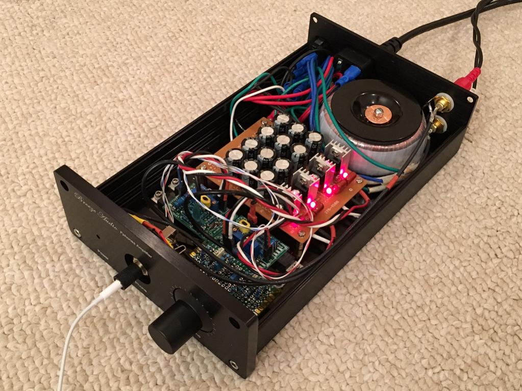
The way I did it, having the inputs pass right by the toroid seems to not pick up any hum at all. The toroid keeps the fields pretty tight and it is a single tangential pass of wire. I am using RG174 coax for that length, not sure if that matters.
My current setup with tooid to the side of the IEC gives a max PCB internal depth of about 150mm. Don't forget you need about 20mm clearance behind front panel for TRS jack and maybe 15mm for volume pot. Although both could fit above a PCB that sat below them.
The case itself has two slots to hold a 140mm wide (1.6mm thick) PCB directly. One slot is 6mm above bottom and other is 12mm above.
Hope that info helps.
Just ran another noise test and the setup with the wires placed where they are now is registering 0.0mV on the Fluke using high quality BNC to banana connector, coaxial cable and BNC to alligator clips to reduce noise pickup from test leads. Max volume pot setting and with no input connected: the amp is literally dead quiet - no way of knowing it is powered on by listening. My MDRV6 cans are relatively sensitive too (106dB/1mW) and I cannot hear anything at all, even when turning volume knob.

So no hum or noise pickup issues with wires going by the trafo.
So no hum or noise pickup issues with wires going by the trafo.
The 560/557 are the TO-92 of the 860/850 with a little higher power dissipation.Yes, I know that your sch uses D44H11 and D45H11, Also BC850/ BC860. Thats the reason why I asked in the post "can someone comment on component chioce of BC560 and TIP31".
For that matter, can you suggest any other replacements for D44/45 pair or BC pair.
here is a first draft of the layout. needs a bit of fine tuning for sure.
reg
Prasi
The TIP31's hfe is lower than the D44H11. Not sure what is the implication to the end result. Since the TIP31 and the D44H11 have the same pinout and package, anyone prefers to use D44H11 still can use the board. In fact, any device with same pinout and similar parameters can be experienced if any wishes. The TIP42C group Y does look a better alternative.
A small personal favor to ask, may I have a +ve only board's .brd when this is final? The reason is that I have a lot of LM317's and not enough LM337
We can communicate using email for this later.Thanks!!
- Home
- Amplifiers
- Pass Labs
- Juma's Head Amp