I always wanted to build a last special amplifier, and wanted it to be big and spectacular.
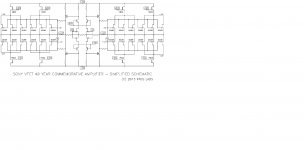
My big example is the '40th Anniversary Sony VFET Amplifier' Nelson presented at CES in 2014.
There are more members who told me they also want to build something like this so I opened my first thread 🙂
I will post a lot of pictures...
What I like to try is building a stereo version of this amp with 1/3 of the VFET's so 8 per channel instead of 24.
Then bias each a bit higher to get a 1/2 40th Anniversary Amp😀
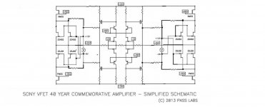
The schematic is the original Sony VFET pt2 article with the two VFET's paralleled and then double it to get a fully balanced amp.
Both sides are connected with R24 to each other instead of to ground.
I will make my own PCb's, chassis and so on, just having a lot of fun.
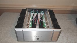
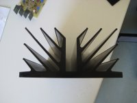
On Ebay I found this nice Pass like heatsinks, so I will build the whole amp in a kind of XA160 chassis.
The heatsinks are 'Oxidised' according to the seller, is that different to 'Anodised'? Does somebody know?
They feel different and look more shiny than what I'm used to.
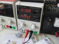
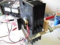
I tested one heatsink with around 100 Watts on the surface, but the surface was too rough, brushed, to get good results. After removing the black 'oxidized' layer and a lot of smooth sanding they transfer the heat better.
I estimate each heatsink can do about 80 Watts of heat. I have six of them so total of 480 Watts. I hope 😱
My big example is the '40th Anniversary Sony VFET Amplifier' Nelson presented at CES in 2014.
There are more members who told me they also want to build something like this so I opened my first thread 🙂
I will post a lot of pictures...
What I like to try is building a stereo version of this amp with 1/3 of the VFET's so 8 per channel instead of 24.
Then bias each a bit higher to get a 1/2 40th Anniversary Amp😀
The schematic is the original Sony VFET pt2 article with the two VFET's paralleled and then double it to get a fully balanced amp.
Both sides are connected with R24 to each other instead of to ground.
I will make my own PCb's, chassis and so on, just having a lot of fun.
On Ebay I found this nice Pass like heatsinks, so I will build the whole amp in a kind of XA160 chassis.
The heatsinks are 'Oxidised' according to the seller, is that different to 'Anodised'? Does somebody know?
They feel different and look more shiny than what I'm used to.
I tested one heatsink with around 100 Watts on the surface, but the surface was too rough, brushed, to get good results. After removing the black 'oxidized' layer and a lot of smooth sanding they transfer the heat better.
I estimate each heatsink can do about 80 Watts of heat. I have six of them so total of 480 Watts. I hope 😱
Attachments
-
 40yearBIG.jpg284.5 KB · Views: 3,589
 -
 Big-Sony-DIY.jpg133.3 KB · Views: 3,518
 -
 NG7_Pass_VFET.jpg251 KB · Views: 3,627
 -
 100Watt.jpg311.7 KB · Views: 1,389
 -
 heat transfer.jpg297.7 KB · Views: 1,465
 -
 sanded.jpg251.1 KB · Views: 1,254
 -
 sink-brushed.jpg244.8 KB · Views: 1,070
 -
 sink-top.jpg200.7 KB · Views: 3,154
 -
 sinks-arrived.jpg325.6 KB · Views: 3,293
 -
 after-sanding.jpg376.3 KB · Views: 1,066
Next the 15mm thick aluminum panels arrived. almost 5 KG each... that's where the heatsinks will be mounted on. The 15 mm sheet will act as a heat distributor. I hope 😱.
On this big sink a T-bar will be mounted, the thickest I could get, 60x60x6mm. On each T-bar there will be 4 MOSFETs and 8 VFETs mounted.
The frontends are done already.....
A lot of work to do for coming winter 😉
On this big sink a T-bar will be mounted, the thickest I could get, 60x60x6mm. On each T-bar there will be 4 MOSFETs and 8 VFETs mounted.
The frontends are done already.....
A lot of work to do for coming winter 😉
Attachments


Fantastic project Walter! I'm looking forward to seeing this progress.
Sightly off topic, what do you guys think of a 1/4 40th anniversary amp with
just 4 vfets per channel? You can use one kit per channel but I don't know
if the bias will be too low to be feasible...
Cheers,
Dennis
Sightly off topic, what do you guys think of a 1/4 40th anniversary amp with
just 4 vfets per channel? You can use one kit per channel but I don't know
if the bias will be too low to be feasible...
Cheers,
Dennis
better not
it'll have much higher voltage envelope than current one
well , at least not safe current one
it'll have much higher voltage envelope than current one
well , at least not safe current one
subscribed

I hope you can borrow me some of your brain cells during the process 😉
I might need them...
all of them ,but two, are already floating through open space .......
so , you can count on these two
so , you can count on these two
Interesting project.
Just looking at the DIY Sony VFET schematic: Taking two per channel - keeping their lower 28 V supply - mirroring one of them and tying the two feedback resisters R4/R4' together instead of connecting them to ground, I would then end up with the same topology, no? And the dissipation of the devices would stay the same as well. Just wondering what added advantage that would have over the unbalanced / unbridged original, all other things remaining equal.
Just looking at the DIY Sony VFET schematic: Taking two per channel - keeping their lower 28 V supply - mirroring one of them and tying the two feedback resisters R4/R4' together instead of connecting them to ground, I would then end up with the same topology, no? And the dissipation of the devices would stay the same as well. Just wondering what added advantage that would have over the unbalanced / unbridged original, all other things remaining equal.
Yes, you would end up with the same topology.
VFET's are at 19.8 Volts, with that schematic. Total voltage swing of 2x 19.8 volts would be a bit high maybe for a single transistor VFET amp.
I was thinking to lower the voltage and up the bias, to get safer behavior.
Maybe the 2 x 24 voltage swing is a bit too much even for my paralleled pair.
Don't know what will be the added advantage, because I never build, or heard a balanced amp 😀 But that is what I want to figure out by building this one😉
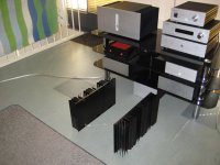
Great project. Where will you be getting the unobtabium Sony VFETs from?
I see two handfuls in a couple of the pictures. Lucky guy.
I always wanted to build a last special amplifier, and wanted it to be big and spectacular.
My big example is the '40th Anniversary Sony VFET Amplifier' Nelson presented at CES in 2014.
There are more members who told me they also want to build something like this so I opened my first thread 🙂
I will post a lot of pictures...
What I like to try is building a stereo version of this amp with 1/3 of the VFET's so 8 per channel instead of 24.
Then bias each a bit higher to get a 1/2 40th Anniversary Amp😀
The schematic is the original Sony VFET pt2 article with the two VFET's paralleled and then double it to get a fully balanced amp.
Both sides are connected with R24 to each other instead of to ground.
I will make my own PCb's, chassis and so on, just having a lot of fun.
Walter,
This is So-o-o Cool!!
Count me as another member interested in making a more powerful VFET amp.
Will you be making extra PCBs to sell to other like-minded Diy'ers??
Keep those great pictures coming.
Kudos to You!!
This weekend, made the PCBs. Because of the total length of 450mm I split them in two separate PCBs so total of four output stages. I cannot illuminate, develop and etch such long 450mm PCBs at home 🙁
Problem is that I bought 2 pieces of photosensitive PCBs 20x30 cm with a month between, resulting in 2 total different PCB colors...grrrrrr 😡
I think I spray paint both PCBs white to get rid of the differences.
Those old IRF240's have 1.5 mm thick pin's 😱
Also drilled very precisely all the holes in one T-bar.
I decided to build one channel first to see how I can bias up, and what heat the T-bar/heatsink combination can dissipate.
So I won't be losing too much time and aluminum resources if I must change the plan and place two T-bars on each heatsink, for instance, to spread the heat better over the whole surface.
Walter
Attachments


Hello Walter
Looks like a great project, I wish that I had enough Vfets to make something similar, but I am still waiting to see if I will be lucky enough to be allocated a kit from the second batch.
However I can tell you that I have found a company here in the UK that will supply aluminium at a very competitive price and will quote online prices for cut to size plate/sheet cheaper than on Ebay. they also have a multiplicity of different profiles such as angle, box, T section etc. There is a shipping charge but if you know everything upfront then you can make a good saving over Ebay, all assuming that they will ship to the Netherlands of course!
Try Buy Aluminium Online : AluminiumWarehouse.co.uk
Lovely PCB work.
John
____________________________________________________________
BOZ, BA-3 Preamp, F4, F5, JLH1969, JLH1996/2003, JLH1970s75W
- Home
- Amplifiers
- Pass Labs
- VFET-X (or my 1/3 40th Anniversary Sony VFET Clone)