... keep handy 9V battery ; bite it and keep bitten all the time you're working with DMM ...
Attachments
I got back to it early this morning doing a few checks.
Good news is that rails and offset look great.
Not-so-good news is that I have not fixed the relay PSU or some related piece completely. I did not want to go replacing parts w/o understanding. I made an attempt to trace the circuit along with taking some comparative values from the good channel.
Here's where to start - L Channel is good, R-Channel is temporarily not activating relays.
L-Channel
Junction of cathode for ZD1 and ZD2: +2V45
ZD2 anode: +0V4
ZD1 anode: (-)25V2
R-Channel
Junction of cathode for ZD1 and ZD2: (-)25V2
ZD2 anode: (-)25V2
ZD1 anode: (-)25V2
Literally the only other thing in that circuit block is C13. It didn't seem roasted, and I thought that would not contribute to what I'm seeing.
I checked board - all replacement parts were installed with correct orientation. Happy to post pics though if needed.
I got lost again.... Any help is appreciated.
Last edited:
do you have +25V at drain of M3?
if yes, replace R25
if not, replace diodes in bridge
+25 at pin 2 - Drain of M3
I replaced R25 yesterday, but changed again a moment ago to be sure.
No change in behavior or readings.
check for shorts, test both zeners with diode check, test do you have short between relay+ and relay- (c13?)
test continuity of all traces between zeners and M3
if you have 27V at C of ZD1 and M3 G, change M3
check that you didn't swap zeners on pcb (don't ask me how I got idea to write that)
test continuity of all traces between zeners and M3
if you have 27V at C of ZD1 and M3 G, change M3
check that you didn't swap zeners on pcb (don't ask me how I got idea to write that)
I replaced both zeners yesterday. Can a diode check be run in-situ? I don't think so, but perhaps?
Zeners to M3
M3 Gate - Pin 1 to Cathode of ZD1 - OK
M3 Drain - Pin 2 - No continuity to either side of either diode - OK
M3 Source - Pin 3 to Anode of ZD2 - OK
I changed M3, ZD1, ZD2, C13, and R25 to all fresh parts since my dodo.
C of ZD1 / M3G: (-)25V
M3D: (+)25V
M3S: (-)25V
I don't think I swapped zeners Marks on them are tiny, but I only took one part from bag - soldered. Put bag away. Took part from other bag, soldered, put bag away.
However, if that's likely, then I can replace quickly. Solder wick is my friend.
Zeners to M3
M3 Gate - Pin 1 to Cathode of ZD1 - OK
M3 Drain - Pin 2 - No continuity to either side of either diode - OK
M3 Source - Pin 3 to Anode of ZD2 - OK
I changed M3, ZD1, ZD2, C13, and R25 to all fresh parts since my dodo.
C of ZD1 / M3G: (-)25V
M3D: (+)25V
M3S: (-)25V
I don't think I swapped zeners
However, if that's likely, then I can replace quickly. Solder wick is my friend.
if you have -25V at M3 gate, change ZD1, it's shorted
we are expecting 27V there ref. to relay negative rail (to remind you , for 12V relays, ZD1 is (12+4)V, for 24V relays ZD1 is (24+4)V, closest value being 27V
prior to that, check that you don't have some short there between pads, it's tight
ZD2 can be anything from 6V2 to 15V, that's mosfet gate protecting thingy
Last edited:
.......
I don't think I swapped zenersMarks on them are tiny, but I only took one part from bag - soldered. Put bag away. Took part from other bag, soldered, put bag away.
....
considering my experience, everything you wrote , in my workshop is no less than 75% chance to solder them in wrong place.......or backwards...... or make short between pads...... or use 1N4148 instead

to remind (us all ) :
Assembly of Japanese Bicycle Require Great Peace of Mind
which means , care and patience and joy, from first to last step in bicycle assembly ; manual ........ I'm always reading afterwards, when deciding where to put that damn big speaker output fuse

Last edited:
All fixed 


Here is what I think happened.
B/C I replaced ZD1 and ZD2 before replacing the Dodo M3 and R25, when I put power to test the replacement - it blew one or both of the zeners.
I had the correct values in place, but I removed them, tested them, and kaput.
Replaced ZD1 and ZD2 - happy little relays.
Zen Mod - Thank you!!!!!
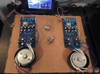
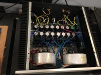
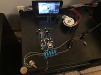
The twins making music with their friend the Babel J2. I said I'd first try it with the BA-3, but I could not wait... 
 Now, I need to get my wife to want a pizza oven, so I can use the board. I like Russellc's temporary pre-amp chassis much better than mine.
re: how she sings. One thing is easy... and nice... she doesn't AT ALL into the Babel J2 with no source or between songs and volume at max (digital attenuation test). Dead silent.
I have been listening to J2 sans pre-amp directly from DAC for over a week. I wanted to "cleanse my palate" before moving to a new pre-amp. I will report some impressions after letting it settle and letting my brain relax.
Once again, THANK YOU!


Thank you!
Right now, I am leaving it as it. However, it is wonderful to know how to do it, if I would like to try. I also know where I could now maybe bodge a pot to play or put in some of the small pins to make it easy to change values.
I am always wondering funny things about the whole chain. If H2 vs. H3 is sugar. Examples of funny thoughts:
If I have (no such thing) perfectly linear pre-amp and add sugar at amp - is that the best way?
If I add sugar at pre-amp and amp has opposite phase H2, does it "cancel"...
If I add sugar at pre-amp and amp has same phase H2, does it compound it?
Until I can measure some fun things from inputs of pre to output of amp(s) - I will leave the beautiful ZM design as is. I have too much too learn.
You've seen what I can do just by trying to test a relay and having clumsy hands


well, remark about adding some sugar was
pretty much general, more applicable to SE iteration than to balanced, simply because autoformer when used balanced is having that inherent SUSY character/function, so not so easy to unbalance things;
so, take that remark with grain of salt, when speaking of balanced
A. there is such thing - Iron Pumpkin; probably not sole or most linear preamp in the world, but certainly example of least harmful one, when speaking both of linearity and signal energy preservation
though - for my liking - that's the approach - least visible (with ears ) preamp , then having what you need of sugar in amp and speakers
that's at least how I'm trying to control things with my non-capable hands
B. yup, it'll cancel
C. yup, it will add
for B and C - that's why recent Papatoy preamps are made as Swiss Knife - you can vary not just THD spectra but phase of it, too
Iron Pre and Iron Pumpkin are not exactly Swiss Knife for these same purposes, being made with sort of opposite approach
pretty much general, more applicable to SE iteration than to balanced, simply because autoformer when used balanced is having that inherent SUSY character/function, so not so easy to unbalance things;
so, take that remark with grain of salt, when speaking of balanced
Thank you!
Right now, I am leaving it as it. However, it is wonderful to know how to do it, if I would like to try. I also know where I could now maybe bodge a pot to play or put in some of the small pins to make it easy to change values.
I am always wondering funny things about the whole chain. If H2 vs. H3 is sugar. Examples of funny thoughts:
A.If I have (no such thing) perfectly linear pre-amp and add sugar at amp - is that the best way?
B.If I add sugar at pre-amp and amp has opposite phase H2, does it "cancel"...
C.If I add sugar at pre-amp and amp has same phase H2, does it compound it?
Until I can measure some fun things from inputs of pre to output of amp(s) - I will leave the beautiful ZM design as is. I have too much too learn.
You've seen what I can do just by trying to test a relay and having clumsy hands

A. there is such thing - Iron Pumpkin; probably not sole or most linear preamp in the world, but certainly example of least harmful one, when speaking both of linearity and signal energy preservation
though - for my liking - that's the approach - least visible (with ears
 ) preamp , then having what you need of sugar in amp and speakers
that's at least how I'm trying to control things with my non-capable hands
B. yup, it'll cancel
C. yup, it will add
for B and C - that's why recent Papatoy preamps are made as Swiss Knife - you can vary not just THD spectra but phase of it, too
Iron Pre and Iron Pumpkin are not exactly Swiss Knife for these same purposes, being made with sort of opposite approach
The twins making music with their friend the Babel J2. I said I'd first try it with the BA-3, but I could not wait...
Now, I need to get my wife to want a pizza oven, so I can use the board. I like Russellc's temporary pre-amp chassis much better than mine.

Cheaper than a chassis. Nice handle to carry by.

Russellc
Absolutely - In more good news, I just got notice that my chassis has shippedI still need a few doodads to ensure that it will be pretty and that I can mount the pot(s) properly with short wire runs and use an extension rod, but it should all be coming together nicely.

Where are you sourcing your extension rod kit from? I usually go with the one from partsconexion. With thinner face plates it isn't an issue.
With the 10 mm front panel, its brass bushing is just long enough to go through and get a few turns of the nut on the other side. Specs at parts connexion dont indicate it is that long, but it is.
I'm using the thinner 3-4 mm face plate this time so it isn't an issue.
Russellc
- Home
- Amplifiers
- Pass Labs
- What's wrong with the kiss, boy?


