I am a latecomer to this thread and am trying to understand its relevance to the FirstWatt amplifiers. From my simulations and builds of various FirstWatt amplifiers (F4, F5, F6, F7) I have found no need for a regulated power supply if a linear supply if built with a sufficient CRC filter. Those designs are quite insensitive to fluctuations in rail voltages.
It sounds like you need to build your power supply twice, once with "CRC" nonregulated topology, and again with active voltage regulation. Then listen to the amplifier with both options and choose the one that kicks the most *** . You're the judge and jury, nobody else's opinion matters.
Very wise words.
I already have plenty of CRC power supplies laying around.
Just need to build up these regulators and connect to F6 and my eSCAPEd Goat amp see what I get in the way of audible improvements.
I am a latecomer to this thread and am trying to understand its relevance to the FirstWatt amplifiers. From my simulations and builds of various FirstWatt amplifiers (F4, F5, F6, F7) I have found no need for a regulated power supply if a linear supply if built with a sufficient CRC filter. Those designs are quite insensitive to fluctuations in rail voltages.
I am anal about this sought of thing.
It's mostly about the output impedance below 100Hz of the basic CRC supply. I don't like it.
To please my requirements, I would want 800,000uF, that's a little expensive, although not out of the question.
In the end the ear will be the judge. If there is no audible difference then that's fine. I'll be happy either way.
Last edited:
I am anal about this sought of thing.
It's mostly about the output impedance below 100Hz of the basic CRC supply. I don't like it.
To please my requirements, I would want 800,000uF, that's a little expensive, although not out of the question.
Given that the damping factor of these amplifiers isn't super high, I am not sure that increasing the voltage regulation at those lower frequencies would make much difference. But I could be wrong.
Given that the damping factor of these amplifiers isn't super high, I am not sure that increasing the voltage regulation at those lower frequencies would make much difference. But I could be wrong.
That's a fair comment. It's not about building a regulator for the lowest common denominator. It's about building a reference regulator that could be used on any amp.
My power buffer I am building has a damping factor of around 120 (without feedback)
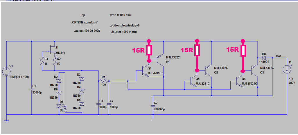
I suggest you install speed-up resistors in the collector circuits of your Sziklai input transistors. These help suck out the base charge of the PNPs when you're trying to drive the output voltage lower. A value of 15 ohms would bias the NPNs at (VBE/15) = 47 milliamps each, which seems like a reasonable starting point. I might also replace the 1 amp rated, output protection diode 1N4004, with a 15 amp MUR1520. Just to be careful.
_
I have gone back to playing with this circuit briefly.
It seems 8 to 10 Ohms is the sweet spot.
Maybe you can compare 8-10 ohms versus Infinity ohms as in post #26. Perhaps it's just a tiny improvement.
It's a significant improvement over the circuit at post 26, especially below 100Hz which is the area that most concerns me.
But it has unusual properties. The higher the constant current draw on the supply the better it's dynamic ac output impedance becomes.
And vice versa at low current draw the performance becomes significantly worse.
From memory number 26 doesn't have this sensitivity to static current draw.
Last edited:
Fortunately the dynamic range of supply current drawn by a class A amplifier (I_max / I_min) is much smaller than the dynamic range of supply current drawn by other amplifier designs: class AB, class B, class G, class D, class H, etc. The idle current of a class A amplifier, with no signal applied and no load attached, is much higher than the idle current of every other amplifier class. This makes it less difficult to design a voltage regulator that works well at both "lowest possible output current" and "highest possible output current."
A ClassAB amplifier has a current draw on one supply rail that varies from 0amperes to peak amperes into the load.Fortunately the dynamic range of supply current drawn by a class A amplifier (I_max / I_min) is much smaller than the dynamic range of supply current drawn by other amplifier designs: class AB, class B, class G, class D, class H, etc. The idle current of a class A amplifier, with no signal applied and no load attached, is much higher than the idle current of every other amplifier class. This makes it less difficult to design a voltage regulator that works well at both "lowest possible output current" and "highest possible output current."
A ClassA push pull amplifier has a current draw on one supply rail that varies from 0amperes to peak amperes into the load.
To me that seems the same. i.e. (I_max / I_min) is the same.
The difference between the two amplifiers' current draw is the quiescent current draw. ClassA is generally higher than ClassAB.
Last edited:
It's a significant improvement over the circuit at post 26, especially below 100Hz which is the area that most concerns me.
But it has unusual properties. The higher the constant current draw on the supply the better it's dynamic ac output impedance becomes.
And vice versa at low current draw the performance becomes significantly worse.
From memory number 26 doesn't have this sensitivity to static current draw.
You are way over my head with this but the first thought that came to mind was using a low R bleeder to increase the load on the regulator.
Of course, this is wasteful but audio components sound best when they are wasteful more often than not.
So when do we see the mystery circuit?")
Just put in a digikey order yesterday. As soon as it is built and tested to confirm performance in the lab I'll post full schematic.
You are way over my head with this but the first thought that came to mind was using a low R bleeder to increase the load on the regulator.
Of course, this is wasteful but audio components sound best when they are wasteful more often than not.
That would most likely work (happy to test it) what would be better in terms of getting something back for the waste would be to increase the bias of the amp as high as your heatsinks allow. You could do a bit of both too I suppose.
Like I said, my skill level is not such that I would ever say what is best.
Figured you had considered it and I do not doubt there is a better way.
The other thing is wasteful does seem to often sound better as unfortunate as that is!
Enjoying reading about your project.
Take care,
Figured you had considered it and I do not doubt there is a better way.
The other thing is wasteful does seem to often sound better as unfortunate as that is!
Enjoying reading about your project.
Take care,
Just put in a digikey order yesterday. As soon as it is built and tested to confirm performance in the lab I'll post full schematic.
I'll look forward to it
...digikey? Do you find them to be the best supplier for folks down our way? I tend to scrounge whatever and wherever I can, be it ebay, jaycar/altronics, RS, and forum members... so most of the boutique parts conversations pass me by
it tends to lead to a fair bit of improvising. If digikey is reasonably priced and has good range, well perhaps I'll change my tune!I wish!
Hahahahaha!
I like the idea that you get to be 'urgent' about this hobby! I get quite obsessed and then life does it's thing and gets in the way... End result is I have a lot of 'urgent' ideas that have taken years. 
There's a long list of tasks in my life... This hobby gets my brain, and life gets the rest!
Good on you! And cheers for the info about digikey.
... and its urgent I buy locally.
Hahahahaha!
I like the idea that you get to be 'urgent' about this hobby! I get quite obsessed and then life does it's thing and gets in the way... End result is I have a lot of 'urgent' ideas that have taken years.
There's a long list of tasks in my life... This hobby gets my brain, and life gets the rest!
Good on you! And cheers for the info about digikey.
- Home
- Amplifiers
- Pass Labs
- Developing a Regulated Dual Rail Power Supply For FirstWatt Amps