Hi Onno,
This guy in Taiwan makes a great 24 step attenuator, with one step as mute. 23 steps is darn good. The preamp gain could be adjusted to have the 23 steps to fall within your volume sweet spot.
http://cgi.ebay.com/ws/eBayISAPI.dll?ViewItem&item=3079706044
Beyond 24 steps, the only reasonable solution I'm familar with is to use a digital controller managing a set of resisters through relays. Combinations of 8 relays/resisters can provide 256 different combinations.
Just a thought,
-David
The best stepped attenuators I've seen are the dual mono kits from Michael Percy. www.percyaudio.com. He uses a great quality 45 position Shallco rotary switch (not made any more) and Holco resistors. Ladder L type. The signal only passes through one resistor. You specify the impedance.
Not cheap but still a good value. $275 US.
Not cheap but still a good value. $275 US.
Hi Onno,
I recently bought a 23-step make-before-break switch at steinmusic in Germany. It costed 56 €. Sounds as a true bargain to me .
.
Steinmusic uses it as a ladder-type attenuator but of course it can also be used as a shunt-attenuator at the output of the BOSOZ. I have made a 2k2 shunt to lower the output impedance of the attenuator.
Hope this helps,
Fox
I recently bought a 23-step make-before-break switch at steinmusic in Germany. It costed 56 €. Sounds as a true bargain to me
. Steinmusic uses it as a ladder-type attenuator but of course it can also be used as a shunt-attenuator at the output of the BOSOZ. I have made a 2k2 shunt to lower the output impedance of the attenuator.
Hope this helps,
Fox
When using it as a shunt, do I remember Nelson saying that you put it between the plus and minus ? If so, whats a good size pot?
In the plans I think 5k is specified. Does that mean that if it is a shunt as I mentioned that 5k will still be the best choice?
I think some saidd this doesn't sound as good. Anyone have that opinion?
I just bought a 26 position switch. Maybe we need a group resistor buy!
Mark
In the plans I think 5k is specified. Does that mean that if it is a shunt as I mentioned that 5k will still be the best choice?
I think some saidd this doesn't sound as good. Anyone have that opinion?
I just bought a 26 position switch. Maybe we need a group resistor buy!
Mark
How about these (41 steps)
http://www.acoustic-dimension.com/attenuators/attanuatorsmain.htm
http://www.acoustic-dimension.com/
Or maybe this one
http://www3.alps.co.jp/cgi-bin/WebObjects/catalog.woa/2/wo/4FBV8TlP4bmSjRdr0va94w/18.2
infinite steps (and expensive, >500 euro)
http://www.acoustic-dimension.com/attenuators/attanuatorsmain.htm
http://www.acoustic-dimension.com/
Or maybe this one
http://www3.alps.co.jp/cgi-bin/WebObjects/catalog.woa/2/wo/4FBV8TlP4bmSjRdr0va94w/18.2
infinite steps (and expensive, >500 euro)
Hi Mark,
The option you describe is also possible but is not a shunt-type attenuator. According to my simulations in Simetrix, 1k is the maximum pot-value for this kind of attenuation. Beware, however, that at (very) low settings the signal is not very well attenuated.
A shunt-attenuator relates to a device with one fixed resistor in line with the signal and after that a resistor between the signal and ground. With a multi-step switch you can change the resistor between signal and ground.
5k is a good value but the lower the better because the output impedance lowers accordingly. In the BOSOZ-article Nelson states that 5k is the lowest you can go. However this 5k-value relates to a ladder-type attenuator. With lower values than 5k you will loose too much gain.
This offers more-than-enough steps. The Aleph P attenuator offers some 48dB attenuation (see the instruction manual). You can attenuate the signal in steps of 2dB and have 52dB attenuation.
Hope this helps,
Fox
When using it as a shunt, do I remember Nelson saying that you put it between the plus and minus ?
The option you describe is also possible but is not a shunt-type attenuator. According to my simulations in Simetrix, 1k is the maximum pot-value for this kind of attenuation. Beware, however, that at (very) low settings the signal is not very well attenuated.
A shunt-attenuator relates to a device with one fixed resistor in line with the signal and after that a resistor between the signal and ground. With a multi-step switch you can change the resistor between signal and ground.
In the plans I think 5k is specified. Does that mean that if it is a shunt as I mentioned that 5k will still be the best choice?
5k is a good value but the lower the better because the output impedance lowers accordingly. In the BOSOZ-article Nelson states that 5k is the lowest you can go. However this 5k-value relates to a ladder-type attenuator. With lower values than 5k you will loose too much gain.
I just bought a 26 position switch.
This offers more-than-enough steps. The Aleph P attenuator offers some 48dB attenuation (see the instruction manual). You can attenuate the signal in steps of 2dB and have 52dB attenuation.
Hope this helps,
Fox
Well, now I'm getting some good information.
OK,
1. If I put the switch between the plus and minus then at lower settings it is almost dead short, Since Nelson mentioned this I guess it doesn't hurt things? Especially the BOSOZ puts out a lot of juice, so I'm worried about hurting it.
2. 1K is the max value? so I should make my switch to mimic a 1k pot?
3. My Shallco switches have 6 poles or wafers, whatever. so my choice is to use 4 wafers only to create 2 ladder type attenuators
which would need to be (shorting) between the plus and minus outputs of two channels. You said that the max value should be 1k, so you are saying that the max output I'll get is a 1 k shorting across the outputs. The minimm output would be like a 1 ohm across them?
Or are you saying that the lowest shorting resister I can use is 1k across the outputs and everything else has to be grater than 1k, up to 5k?
OR
4. use 4 wafers to make 4 series attenuators, 2 for each channel
but make 'em 5k and each terminal gets it's own attenuator
5. I'm leaning toward option 3. That way I have a ladder switch, only one resistor in the signal path, and I can use less resistors, so better quality ones. The question is wots better : series attenuators but one for each output, or ladder type that shorts the outputs?
6. I think I'm pretty confused still.....
Mark
Hi Mark,
The dead short is not going to hurt anything. The + and - signal are 180 degrees shifted in phase and therefore cancel each other out. Beware however that due to the design of the BOSOZ the + and - signal differ in amplitude. As a result, a zero volume setting (max. attenuation) is virtually impossible.
Yes.
When you opt for attenuation by shorting the + and - signals, you do not need a ladder-attenuator. Just put 1 resistor between the two signal-polarities.
The highest will be an infinite resistor, which of course cannot be bought in stores . Just use air! The switch position before this infinite resistor should contain a 1k-resistor. This implies that, apart from the infinite-resistorless resistor, 1k is the highest resistor value in your attenuator.
For this type of attenuator you only need two wafers: one for each channel.
I am lost...
Where are the trees in this forrest?
So am I This stuff can really drive you nuts. In case you want to dig deeper into this problematic, you should check the website of Goldpoint. Goldpoint offers a good explanation of series, ladder and shunt attenuators. Unfortunately, the "balanced-attenuator", which shorts the + and - signal of one channel, is not elaborated upon.
Hope this helps,
Fox
1. If I put the switch between the plus and minus then at lower settings it is almost dead short, Since Nelson mentioned this I guess it doesn't hurt things? Especially the BOSOZ puts out a lot of juice, so I'm worried about hurting it.
The dead short is not going to hurt anything. The + and - signal are 180 degrees shifted in phase and therefore cancel each other out. Beware however that due to the design of the BOSOZ the + and - signal differ in amplitude. As a result, a zero volume setting (max. attenuation) is virtually impossible.
2. 1K is the max value? so I should make my switch to mimic a 1k pot?
Yes.
3. My Shallco switches have 6 poles or wafers, whatever. so my choice is to use 4 wafers only to create 2 ladder type attenuators
When you opt for attenuation by shorting the + and - signals, you do not need a ladder-attenuator. Just put 1 resistor between the two signal-polarities.
Or are you saying that the lowest shorting resister I can use is 1k across the outputs and everything else has to be grater than 1k, up to 5k?
The highest will be an infinite resistor, which of course cannot be bought in stores
. Just use air! The switch position before this infinite resistor should contain a 1k-resistor. This implies that, apart from the infinite-resistorless resistor, 1k is the highest resistor value in your attenuator.For this type of attenuator you only need two wafers: one for each channel.
4. use 4 wafers to make 4 series attenuators, 2 for each channel
I am lost...
5. I'm leaning toward option 3. That way I have a ladder switch, only one resistor in the signal path, and I can use less resistors, so better quality ones. The question is wots better : series attenuators but one for each output, or ladder type that shorts the outputs?
Where are the trees in this forrest?
6. I think I'm pretty confused still.....
So am I
This stuff can really drive you nuts. In case you want to dig deeper into this problematic, you should check the website of Goldpoint. Goldpoint offers a good explanation of series, ladder and shunt attenuators. Unfortunately, the "balanced-attenuator", which shorts the + and - signal of one channel, is not elaborated upon.Hope this helps,
Fox
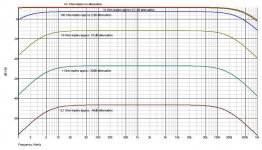
Just added a graph to illustrate the resistor values yo may need for a balanced attenuator. They need to be very low!
Forget what is on the y-axis. What matters in this picture are the relative vertical distances. I have added the approximate attenuation values. From these values you can deduce the 'law'governing the balanced attenuation Just remember that all the attenuation values in dB should be on a straight line with a specific slope. The x-axis should list the resistor values....
Forget what is on the y-axis. What matters in this picture are the relative vertical distances. I have added the approximate attenuation values. From these values you can deduce the 'law'governing the balanced attenuation
Just remember that all the attenuation values in dB should be on a straight line with a specific slope. The x-axis should list the resistor values....Attachments
Thank you
to all of you
David
Labjr
Fox
Mark
Duck-Twacy
after 1,5 years of looking around, first in the german forum audiomap
then in this forum I learned a lot. Quiet askings here and there.....
because I'm a bloody, bloody beginner in EE.
Now I am able to fix my mind and I will take two separate volume-
switches with 10k at the output (P3 + P4) at the BZLS with shunted
building. All the other hints have a good background but if I will
follow the hints I'm confused and I will be there where I'have been
before 1,5 years.
And it must be payable !
Now I'm waiting to get an offer from electro-nc. I hope it will be
not to expensive ! It will have 32 contacts.
Onno
Ps . My question to NSF Controls could not be answered ?
Hi Onno,
A 10k shunt at the output of the BOSOZ is a bit high if you ask me. It is better to opt for 5k or lower. It is not so difficult to calculate the resistor values in a spreadsheet program :
attenuation [dB] = 20 * log (1 + R shunt / R ground)
Given the attenuation and the R shunt, you can calculate R ground.
attenuation / 20 = log (1 + Rs / Rg)
1 + Rs / Rg = 10^(dB/20)
Rg = Rs / (10^(db/20) - 1)
Please, show us your design when it is ready. I'm sure other members of the forum will be quite eager to learn how to deal with this stuff. I know I did a year ago
Cheers,
Fox
>Variac
Instead of ladder type go for shunt type. Sonically it is really not worth to go for ladder type with twice the resistors and twice as many decks as for shunt type (8 decks attenuator for balanced version). 10K at the output of either P 1.7 or P 1.0 doesn't work well. 5K works good and the lower value up to 2K still works well if not better.
These are the Dale RN60D resistor values for 5K attenator
Instead of ladder type go for shunt type. Sonically it is really not worth to go for ladder type with twice the resistors and twice as many decks as for shunt type (8 decks attenuator for balanced version). 10K at the output of either P 1.7 or P 1.0 doesn't work well. 5K works good and the lower value up to 2K still works well if not better.
An externally hosted image should be here but it was not working when we last tested it.
An externally hosted image should be here but it was not working when we last tested it.
These are the Dale RN60D resistor values for 5K attenator
Attachments
Nelson suggested that a good value for the output pot on the aleph p1.7 would be between 1k and 2k, if i'm not wrong.
So i would like to use an average...and so... 1.5k out pot woudl work fine.
Could you please post the formula to calculate the values of the resistors?
Hey, a curioustity...i've been searching quite a lot on google to find an elma rotary switch.....where did you find it? how much did you pay for it? ...i would be interested on 2 separates stereo deck.
About the ladder type...what i have read so far about this, it's that the ladder should have better performance than the shunt type and obviously the serie type.
Have you had a chance to directly compare on your preamplifier te 2 types?
anybody may post the shematich for a latter type?
thanks a lot for the hints.
Best,
Stefano.
I found this link that expains very well the different types
http://www.goldpt.com/how.html
i have one observation to make:
accordingly with the schematics
the serie type seems to have the advantage of having a constant input inpedence but the drawback of having the signal path passes throught a lot of resistors.
coversely, the shunt type has a variable in-out inpedence but the signal passes throught only two active resistors at each step.
Finaly the ladder type...it has the advantage of the constant input resistor like the serie type and the the twp active res each step like the shunt type.
Therefore theorically it seems much better.
the only drawback is the cost.
But in this website they show how to make a balnced att latter type using a 4 deck rotary sw.
I'll take a better look.
They are using electoswitch that i have read on te forum.....but nelson said that he regreated to have bought a stock of this electroswitch.
Unfortunally i don't get the reasons....i'll just trust what he says and that's why i'm ooking for something else.

part connection has the elma but i think is 6positions...
thanks a lot for the hints.
Best,
Stefano.
http://www.goldpt.com/how.html
i have one observation to make:
accordingly with the schematics
the serie type seems to have the advantage of having a constant input inpedence but the drawback of having the signal path passes throught a lot of resistors.
coversely, the shunt type has a variable in-out inpedence but the signal passes throught only two active resistors at each step.
Finaly the ladder type...it has the advantage of the constant input resistor like the serie type and the the twp active res each step like the shunt type.
Therefore theorically it seems much better.
the only drawback is the cost.
But in this website they show how to make a balnced att latter type using a 4 deck rotary sw.
I'll take a better look.
They are using electoswitch that i have read on te forum.....but nelson said that he regreated to have bought a stock of this electroswitch.
Unfortunally i don't get the reasons....i'll just trust what he says and that's why i'm ooking for something else.
part connection has the elma but i think is 6positions...
thanks a lot for the hints.
Best,
Stefano.
Stefano
The intenet is full of formulas, spreadsheets and Java calculators for attenuators. In fact this issue is so trivial, it would only take you a few minutes to create your own spreadsheet. Can you not make a little effort?
The value of the output attenuator in the 1.7 is non-critical for the amlifying stage. In my view the shunt attenuator chosen by zygibajt is the best choice as it offers a very low output impedance over most of the range. And involves only two resitors per position. The higher value allows for smaller output caps.
I have tried various configurations, including a 600ohm T-network and while they all sounded slighlty different, the difference is easily swamped by the type of input/output caps. Going overboard with the choice of attenuator would be more justified in a less coloured, dc coupled circuit.
yes...sorry i tried to edit the first post because sfter have read that link on the different type of attenuator it was preatty clear how to calculate the values.
therefore i tried to editate the post and delete some parts but 30minutes were already passed.
Anyway, i do agree about the dccpupling.
For this project i used auricap capacitor that seem to be very neutral parts.
I personally think that a costant impendence is better in general whether you use it in a dc coupled or not.
what i was trying at this point to figure out was the possibility to use 4 decks for a latter type, so i'm tring to read the description of hoe they built it and see if i could find a 4 deks 23 pos elma switch.
I noticed that parconnection doesn't have dale resistors anymore...
- Status
- This old topic is closed. If you want to reopen this topic, contact a moderator using the "Report Post" button.
- Home
- Amplifiers
- Pass Labs
- stepped attenuator