I'm confused now ....... what is a scope of questions - solving supply for buffer, or someting with GND?
GND is established in said amp, by someone smarter than we Greedy Boyz are, so please bugger off of GND
regarding buffer PSU - it's simple - choose your poison - making small bipolar PSU for said buffer, or insert it in monopolar amp PSU, but then you need small cap on buffer input and bigger cap on buffer output
go see Singing Bush, Schade iteration, to see one way

Since the toroid I'm using has 45v,18v, and 12v secondaries I'm going to build a small bipolar supply for the buffer. I may have caused a lot of confusion here by misinterpreting Pa's remarks about grounding the buffer circuit.
Regards,
Dan
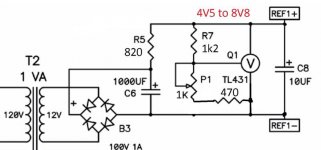
Using one of these for each channel AN-8445 - 800VA 45V Transformer - AnTek Products Corp. Thinking of building four of these TL431's. One for the bias of each channel and then a second pair (with values adjusted) to supply the +/- 12vdc to each buffer.

Regards,
Dan
Regards,
Dan
Attachments
just tie those 18 and 12V, common tap is to connect to main GND
after rect. and smoothing you'll get unequal rails, but no problem for regs, current is tiny anyway
sole TL431 regs, for buffer rails - not to my liking, not enough current capacity there
use LM317/337 , don't forget to shunt their outputs with additional 15mA , buffer itself is small burden
after rect. and smoothing you'll get unequal rails, but no problem for regs, current is tiny anyway
sole TL431 regs, for buffer rails - not to my liking, not enough current capacity there
use LM317/337 , don't forget to shunt their outputs with additional 15mA , buffer itself is small burden
Dan,
I used the same PS for the gate supplies. I found however that I needed to make P1 5k, which allowed me to go lower than the 4.7V that is on the original BAF2015 schem. Just something to keep in mind. On mine, one channel needed 3.78V, the other 3.65V. The 5k for P1 allows to go as low as 3.08V.
-John
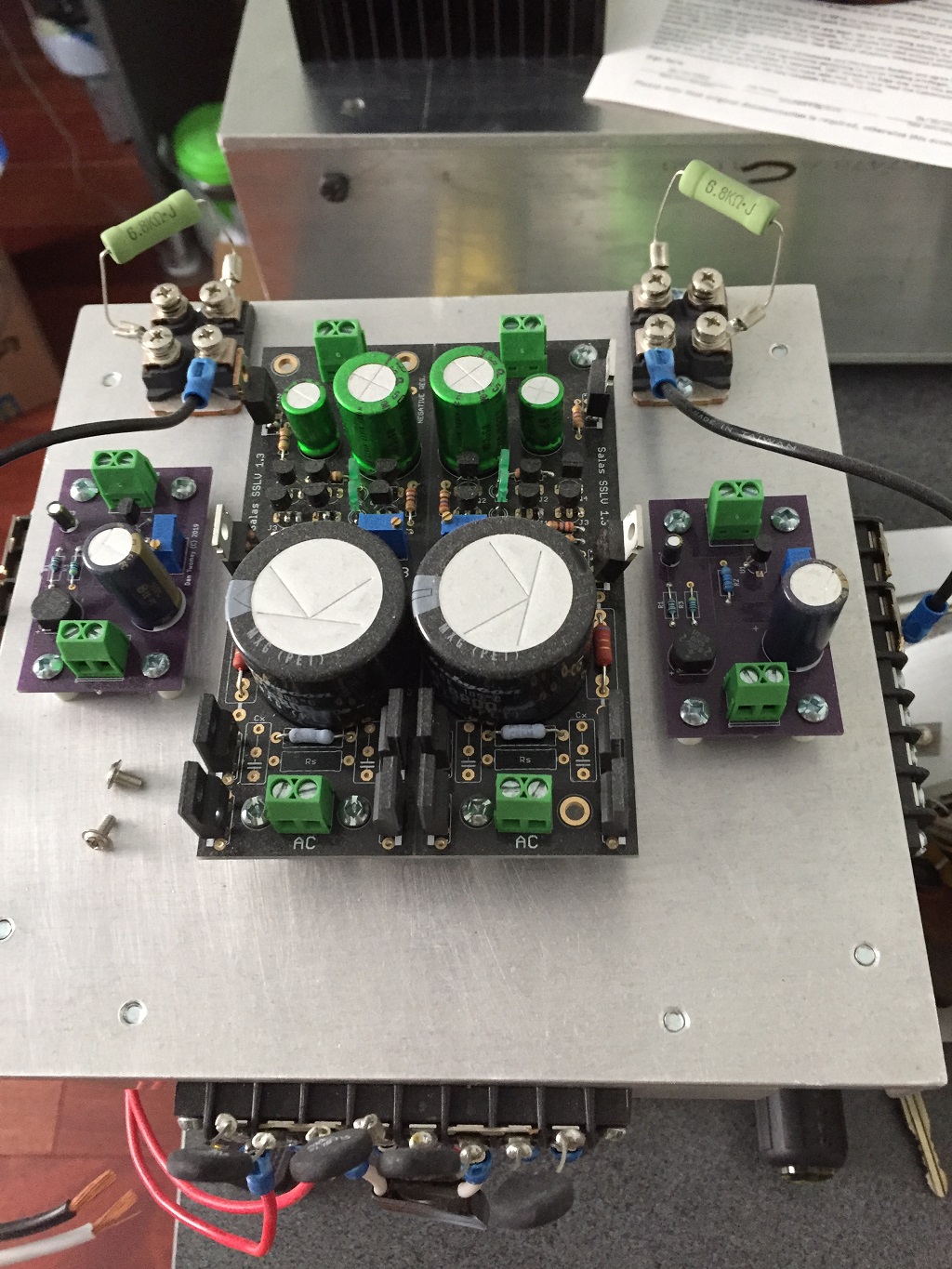
Two lucky breaks for me as seen in the picture below. The two outboard PCBs are the TL431 bias circuits and I have spare PCBs if I want to make up a set that has a different voltage range. Also, ZM suggested a regulator with more current for the buffers. Although a little overkill, I just happened to have a pair of SALAS regulators kicking around so in they went.
Regards,
Dan
Regards,
Dan
Attachments

I have now tested some of my posted circuits:
I tested #1162 and it both worked beautifully and not awful at the same time.
I could dial in the bias and with no feedback I got huuuuge amounts of gain, but when I start adding feedback the FET started to oscillate like crazy.
After fixing the input transformer primaries to be in parallel such that I actually get a significant amount of current feedback it starts to oscillate immediately on all the circuits I have tested. All the capacitively coupled circuits that is.
I'm not sure how to proceed. My understanding is that I need to use voltage feedback @ DC to stabilize it, but that would complicate the circuit.
Which I got from Amplifier topologies for current-drive | Current-Drive - The Natural Way of Loudspeaker Operation
#1 If I do that then I basically have to lift the input to the same DC potential as the output. And even then it doesn't solve my problem that my output DC level is not perfectly level from startup to shutoff. With cap coupled output it's not an issue as the thump is managable but I'm not sure if loading the transformer with lots of DC @ startup, shutoff and during any potential drift is a good idea.
#2 The other option I know of is to use DC a coupled output. I fixed the bias in my DC coupled version such that it's a bit more stable but still pot-controlled and the bias is pretty stable... as long as we ignore the 22V thump at startup
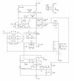
So yeah, I think a servo is absolutely necessary for the DC coupled route. I did try to build the servo that Zen Mod had simulated but I couldn't get it to work properly. That might be my fault though, so tomorrow I'm planning to look more closely at it and see if I can get it working. See attachment for the circuit I built.
#3 A third option I'm considering is to build a normal voltage source amp with differential input, say the Aleph J or Babelfish J2 and then slightly reduce the voltage feedback and wrap a current feedback loop around it. It is more complicated though than this single stage amp.
Anyone know a more simple way to get a current feedback loop working?
Or the best solution would be if I there exists a magic transistor which I could connect in say common-drain configuration but would use the internal feedback to give me a high output impedance power buffer instead of a low output impedance one. I don't know of any such transistors though =)
I tested #1162 and it both worked beautifully and not awful at the same time.
I could dial in the bias and with no feedback I got huuuuge amounts of gain, but when I start adding feedback the FET started to oscillate like crazy.
After fixing the input transformer primaries to be in parallel such that I actually get a significant amount of current feedback it starts to oscillate immediately on all the circuits I have tested. All the capacitively coupled circuits that is.
I'm not sure how to proceed. My understanding is that I need to use voltage feedback @ DC to stabilize it, but that would complicate the circuit.
Which I got from Amplifier topologies for current-drive | Current-Drive - The Natural Way of Loudspeaker Operation
#1 If I do that then I basically have to lift the input to the same DC potential as the output. And even then it doesn't solve my problem that my output DC level is not perfectly level from startup to shutoff. With cap coupled output it's not an issue as the thump is managable but I'm not sure if loading the transformer with lots of DC @ startup, shutoff and during any potential drift is a good idea.
#2 The other option I know of is to use DC a coupled output. I fixed the bias in my DC coupled version such that it's a bit more stable but still pot-controlled and the bias is pretty stable... as long as we ignore the 22V thump at startup
So yeah, I think a servo is absolutely necessary for the DC coupled route. I did try to build the servo that Zen Mod had simulated but I couldn't get it to work properly. That might be my fault though, so tomorrow I'm planning to look more closely at it and see if I can get it working. See attachment for the circuit I built.
#3 A third option I'm considering is to build a normal voltage source amp with differential input, say the Aleph J or Babelfish J2 and then slightly reduce the voltage feedback and wrap a current feedback loop around it. It is more complicated though than this single stage amp.
Anyone know a more simple way to get a current feedback loop working?
Or the best solution would be if I there exists a magic transistor which I could connect in say common-drain configuration but would use the internal feedback to give me a high output impedance power buffer instead of a low output impedance one. I don't know of any such transistors though =)
Attachments
Last edited:
You seem to be reinventing the F2J.
FIRST WATT
Pertty much yeah =)
Problem with the F2J topology is that the degenerative feedback alone isn't enough to reduce distortion low enough to be usable as a 25-40W amp. For that I need a traditional current feedback loop or find some more fancy transistor that has less distortion.
Or experiment further with a cascoding topology like the F3 / ZenV9. With cascoding I might be able to get distortion low enough without a feedback loop. I do have a stash of 10x LU1014D and 2x 2sk82 lying around I could experiment with.
you have separate secondaries at big Donut, for buffer PSU?
Yes.
I tried again and did find a mistake in the servo circuit in #1190. I switched in the inputs of the TL081 opamp. Even with that fixed it still didn't work. The 5v regulator seems to create a 5v reference so at least that part seems to work.
Worth noting also that at the moment I'm not using beast mosfet or R100s but rather IRFP150s both for top and bottom.
Which makes want to start asking about how the servo bias actually works so I can try to understand what is going wrong:
My guess of how it works is:
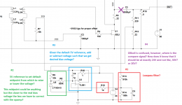
#1 is a lowpass filter since we want to correct only the DC.
#2 the 5v reference creates a kind of default midpoint. This could be any voltage but close-ish to target voltage is better since then the TL081 has to correct less?
#3 The TL081 opamp outputs the difference from the 5V midpoint to the X voltage and outputs this as the bias voltage?
On #3 is where I don't really know what happens. Mostly I'm confused since the servo bias only really has a single input, X. How does it know to make the bias exactly such that the voltage at output is half of the rails? Shouldn't it need some input of the "ideal" voltage target such that it knows when to stop?
Now that I think about it if I remember correctly I got 6V difference from GND with +- 24V rails. Maybe if I learn how to set the target voltage I can get it working.
Worth noting also that at the moment I'm not using beast mosfet or R100s but rather IRFP150s both for top and bottom.
Which makes want to start asking about how the servo bias actually works so I can try to understand what is going wrong:
My guess of how it works is:
#1 is a lowpass filter since we want to correct only the DC.
#2 the 5v reference creates a kind of default midpoint. This could be any voltage but close-ish to target voltage is better since then the TL081 has to correct less?
#3 The TL081 opamp outputs the difference from the 5V midpoint to the X voltage and outputs this as the bias voltage?
On #3 is where I don't really know what happens. Mostly I'm confused since the servo bias only really has a single input, X. How does it know to make the bias exactly such that the voltage at output is half of the rails? Shouldn't it need some input of the "ideal" voltage target such that it knows when to stop?
Now that I think about it if I remember correctly I got 6V difference from GND with +- 24V rails. Maybe if I learn how to set the target voltage I can get it working.
Attachments
well, you're trying servo set for 5V reference on one input , to govern your circuit which is having 0V pushing at second input of servo - you have dual rails, while servo I drew is made to set half of one rail on output
toss 5V reference out, connect that input to gnd
feed OP with dual rails
remove R9
remove R14
all that ref. to your last pic, post #1194
toss 5V reference out, connect that input to gnd
feed OP with dual rails
remove R9
remove R14
all that ref. to your last pic, post #1194
well, you're trying servo set for 5V reference on one input , to govern your circuit which is having 0V pushing at second input of servo - you have dual rails, while servo I drew is made to set half of one rail on output
toss 5V reference out, connect that input to gnd
feed OP with dual rails
remove R9
remove R14
all that ref. to your last pic, post #1194
Cool, I think I understand now:
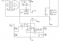
So basically R13+R14 works as a voltage divider translating 30V -> 5V. This is then compared to the 5V refence.
One further thing though:
The TL081 maximum voltage is 36V so if I feed it with +-24V it will probably not feel that well.
I believe I should be able to counterract this by just keeping the opamp at -24V to 0V and then shifting the input voltages down towards -24V.
This schematic uses the same attenuator as yours and shifts the voltage down by 1/6. My guess is that if I find it too slow during startup I could make R14 = R13 making the attenuation 1/2.
Attachments
nope
read again what I wrote
use 7815/7915 to feed OP, and do with resistors as I wrote
can't catch what you want with 1/6 of negative !!! rail at ref.side of servo, when you want 0V at output node ?
put ref input to gnd, sense input to output node, and funny critter will do everything in its power to equalize what's on its inputs
nope
read again what I wrote
use 7815/7915 to feed OP, and do with resistors as I wrote
can't catch what you want with 1/6 of negative !!! rail at ref.side of servo, when you want 0V at output node ?
put ref input to gnd, sense input to output node, and funny critter will do everything in its power to equalize what's on its inputs
It seems I did not understand =)
Next try:
Attachments
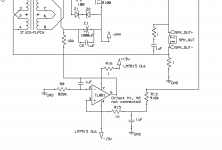
now, it seems that you understood
Yay
And thanks for the help! And while I'm at it, what is the purpose of R16? I assume to reduce the current through the opamp but if I understand correctly and the current through the it is in the miliamp range then the voltage drop across it will be extremely small.
- Home
- Amplifiers
- Pass Labs
- 50w Single-Ended BAF2015 Schade Enabled