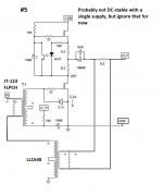
I got one of my signature potentially dumb ideas again!
I've been toying with the idea of doing a cascoded version with maybe a 2sk82 on the bottom but I know how to do that and how to get it to work.
My question is if the opto CCS will work with say Zv9 cascoding out of the box or if I need to use a more fancy biasing scheme. I asked a while ago about using an optocoupler on the bottom and it was a certified dumb idea there, so it might be the same here =)
Attachments
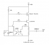
I got one of my signature potentially dumb ideas again!
I've been toying with the idea of doing a cascoded version with maybe a 2sk82 on the bottom but I know how to do that and how to get it to work.
My question is if the opto CCS will work with say Zv9 cascoding out of the box or if I need to use a more fancy biasing scheme. I asked a while ago about using an optocoupler on the bottom and it was a certified dumb idea there, so it might be the same here =)
It wont work like that, in this case, optocoupler is not regulating the bias, but Vds of lower jfet..
The THF-51S amps are in my system and are making music....
The amps are certainly no worse than the TAN-5550, and I think are better in a number of ways.
It is difficult to do a fair comparison, but one thing jumps out.
The transients, such as percussion, seem better.
Anyway always try speakers reverse polarisation. Sometimes is a nice surprise.
After my experience is interesting to use different connection to CCS resistors, change from point C to D.
Easy and reversible modification and give very different sonic signature from the same amplifier.
Who can be attractive specially for woofers shake
") Enjoy
EnjoyAttachments
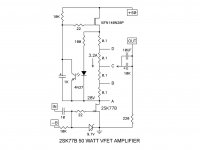
I've been listening to the amps in my system for more than a week now, so I can make some comments about the sound.
The THF-51S amps are used in a biamped system to power the JBL 2225 woofers in about 9 cubic feet vented boxes. The top end, JBL 2445 drivers, 2397 horns, and 2405 tweeters are powered by a 2SJ28 L'Amp with 193V inductor. Previously, I was using a Sony TAN-5550 VFET amp for the bottom end. I did a major rebuild on the TAN-5550, replacing all the electrolytic capacitors, the "death" diodes, a lot of resistors, and new mica insulators for the VFETS, so it was in good operational condition. The TAN-5550 is rated at 50 W per channel.
The THF-51S' operating point is 34.5V at 2.2A. My CCS uses 6 x 0.1 Ohm resistors and the output is at the midpoint of the group. I did not change the speaker phasing but did do a frequency sweep to check that it was not out of phase with the top end.
My speakers are spaced about 5.5 metres apart and are in the room corners. The JBL 2397 horns work well in this arrangement and fill the room with sound. I like a presentation where I feel like I'm there in the venue. I'm not picky about imaging.
The biggest impression that I get with the new amps is the bass impact. I have measured the overall frequency response and it is not much different that with the Sony TAN-5550 but listening to music, the bass impact is significantly greater. I did not expect that and was pleasantly surprised.
I believe that the overall sound has also improved. The music is presented as a whole entity. The "image" is seamless, very coherent. I think that having single ended VFET amps for both the top and bottom in the biamped system contributes to that. My preamp uses 01A tubes single-ended as well, so the system is consistent. The overall sound is very powerful.
I will try different arrangements, as Soundhappy suggests, in the next little while. For now, I'm enjoying the music.
Last edited:
I got one of my signature potentially dumb ideas again!
I've been toying with the idea of doing a cascoded version with maybe a 2sk82 on the bottom but I know how to do that and how to get it to work.
My question is if the opto CCS will work with say Zv9 cascoding out of the box or if I need to use a more fancy biasing scheme. I asked a while ago about using an optocoupler on the bottom and it was a certified dumb idea there, so it might be the same here =)
I think it will work. Controlling the Vds of the LU1014 will regulate
bias since that Jfet has high current dependence on Vds at lower
voltages. Of course you have to ask whether that is more effective
than just controlling the big Mosfet directly.
Another thing I've been wondering:
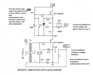
Does the transformer input impedance multiplication trick still work when using current feedback instead of voltage feedback? I want to build a current source variant as my speaker likes high output impedance.
Hockey pucks look kinda fun though... so would be cool if it works in that configuration too =)
Attachments
I think it will work. Controlling the Vds of the LU1014 will regulate
bias since that Jfet has high current dependence on Vds at lower
voltages. Of course you have to ask whether that is more effective
than just controlling the big Mosfet directly.
But isn't the optocoupler doing just that, controlling the big mosfet directly since the Jfet gate is connected to the bottom of RS and not the top of the opto?
If I've understood correctly the schmatic should with respect to DC be equivalent to the normal opto circuit but with an extra current dependent resistor between RS and the CCS-mosfet source.
Or at least, that is what I hope it does, but that does not mean it actually does
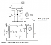
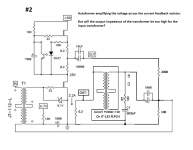
In my experiments I have gotten the circuit to kinda work with current feedback but at the same time kinda not.
I got the circuit stable, but that's not saying much as the amount of current feedback actually used was pretty low. I got maybe 3-6 dB of current feedback which is a bit less than I want =)
It works perfectly If I increase the R of the current feedback resistor but I have 4 ohm speakers so even 1 ohm is pushing it higher than I would like.
So my take on it is that I want to amplify the voltage across that resistor before feeding it back into the input transformer. My first idea was to use a simple jfet but then it inverts the phase and I have to fiddle with DC offset.
Then I got one of my certified crazy ideas again: could I just use more transformers?
I have quite a few Lundahl LL1540 which are pretty similar to the Jensen JT-123-FLPCH and 2 Edcor PC600-15K lying around anyway =)
This adds more impedance matchings though so I'm not sure it will work.
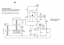
#1 is to raise the gain of the amp to ~ 30 - 35 dB and place the transformer in between the input transformer and the mosfet. In this case my guess is that the increased capacitance of the autoformer will wreck havoc on a beast mosfet or even a normal mosfet like the IRFP240 in common-source mode making this a non-option but might as well throw out the idea for review =)
#2 would be to amplify the voltage across the current feedback resistor. Will the input transformer play nice in this case though?
EDIT:
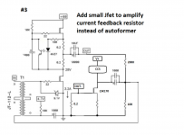
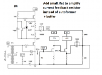
Might as well post idea #3 and #4: adding an amplifying jfet and in the case of #4 also a buffer.
But thats way more complicated than just using transformers. It makes a beautifully simple circuit not as simple and beautiful anymore.
And something I forgot in the schematics: I will fiddle with making the input transformer parallel instead of in series, as effectively increases the current feedback voltage : input voltage ratio. On my F6 amp that worked but I had to use an 1 ohm resistor to get enough feedback, so these ideas are still valid as they would let me reduce the resistance of the feedback resistor.
I got the circuit stable, but that's not saying much as the amount of current feedback actually used was pretty low. I got maybe 3-6 dB of current feedback which is a bit less than I want =)
It works perfectly If I increase the R of the current feedback resistor but I have 4 ohm speakers so even 1 ohm is pushing it higher than I would like.
So my take on it is that I want to amplify the voltage across that resistor before feeding it back into the input transformer. My first idea was to use a simple jfet but then it inverts the phase and I have to fiddle with DC offset.
Then I got one of my certified crazy ideas again: could I just use more transformers?
I have quite a few Lundahl LL1540 which are pretty similar to the Jensen JT-123-FLPCH and 2 Edcor PC600-15K lying around anyway =)
This adds more impedance matchings though so I'm not sure it will work.
#1 is to raise the gain of the amp to ~ 30 - 35 dB and place the transformer in between the input transformer and the mosfet. In this case my guess is that the increased capacitance of the autoformer will wreck havoc on a beast mosfet or even a normal mosfet like the IRFP240 in common-source mode making this a non-option but might as well throw out the idea for review =)
#2 would be to amplify the voltage across the current feedback resistor. Will the input transformer play nice in this case though?
EDIT:
Might as well post idea #3 and #4: adding an amplifying jfet and in the case of #4 also a buffer.
But thats way more complicated than just using transformers. It makes a beautifully simple circuit not as simple and beautiful anymore.
And something I forgot in the schematics: I will fiddle with making the input transformer parallel instead of in series, as effectively increases the current feedback voltage : input voltage ratio. On my F6 amp that worked but I had to use an 1 ohm resistor to get enough feedback, so these ideas are still valid as they would let me reduce the resistance of the feedback resistor.
Attachments
-
 Hockey Puck circuit current feedback stable.png168.6 KB · Views: 261
 -
 #2 Hockey Puck circuit current feedback current feedback resistor autoformer.png179.9 KB · Views: 106
 -
 #1 Hockey Puck circuit current feedback cascaded autoformer.png185.8 KB · Views: 243
 -
 #3 Hockey Puck circuit current feedback current feedback resistor jfet.png169.5 KB · Views: 109
 -
 #4 Hockey Puck circuit current feedback current feedback resistor jfet buffer.png171.5 KB · Views: 119
Last edited:
Swap positions of the current feedback resistor and speaker in post #1147, you may have to attenuate it!
But won't that just make it a normal low-ish output impedance voltage feedback amplifier? Since then the feedback signal will correct the voltage over (speaker + resistor) instead of just (resistor).
Won't it be pretty much the same as If I used the normal voltage feedback schematic and added a series resistor to the output to raise output impedance to the value of the resistor?
As I see it, if you look at the speaker and feedback resistor, its a potential divider between the output and ground. Flip it upside down and its still a potential divider, all that's changed is the ratio.
The feedback to the transformer is a voltage, it always was.
It's current feedback because you are monitoring the voltage developed across a resistance caused by the current flow.
Having said that, because the impedance of the speaker is not constant with frequency, the feedback signal will vary, flipping the position of the resistor and speaker will cause the variation to invert.
As I see it, if you look at the speaker and feedback resistor, its a potential divider between the output and ground. Flip it upside down and its still a potential divider, all that's changed is the ratio.
The feedback to the transformer is a voltage, it always was.
It's current feedback because you are monitoring the voltage developed across a resistance caused by the current flow.
Having said that, because the impedance of the speaker is not constant with frequency, the feedback signal will vary, flipping the position of the resistor and speaker will cause the variation to invert.
Sure, but the feedback I want to send to the input is the voltage across that resistor, not that resistor + voltage across the speaker which as you said varies.
I could flip it to the top but I still only have the voltage across said resistor to play with. And since now the feedback voltage is now floating above ground I'd have to use a transformer to bring it down to ground reference for the input transformer.
And while I could get ground loaded operation that way instead of having the speaker float above ground, I'm not connecting the speaker to anything afterwards so a floating ground isn't an issue. It would make design phase easier though as I would have an easier time measuring as I don't have to fiddle with transformers for my sound card =)
Attachments
Last edited:
The voltage would be across the speaker, not the resistor & speaker.
The voltage varies even if you measured it across the resistor.
Yes, but the voltage across the resistor varies only as a function of the current through the speaker. The voltage across the speaker varies as a function of the current & the stroke position.
It is this stroke impedance variation I want to correct with the current feedback, hence I want the correcting signal to only be dependent on the current of the speaker -> voltage across the resistor.
Which in practice means I want the output impedance of the amplifier to be large relative to the speaker, ideally 10x or more. Thus the input signal controls the current through the speaker, not the voltage across it.
Servo schematic by Zen Mod
Also another unrelated question, more specifically to Zen Mod
 who cooked up the servo circuit:
I did test using a bipolar +-24V supply with a F6-ish bias supply for the lower fet and yeah it works fine in steady-state there is a huuuuge DC offset on startup... pretty much this.
I'm wondering if the servo would take care of this startup DC-offset issue. If not then I'll probably revert to cap coupled output.
DC coupled output makes my current feedback scheme more simple... and as I have to have a DC-coupled buffer I need +- 24V anyway so it would be nice to make the amp output DC-coupled too.
And IF the servo would solve the DC offset on startup, I have questions about the LT1634-5 in the schematic. Is it this part? My local store doesn't have that part, is it OK to swap it out for any Fixed Shunt 5V Voltage Reference like say... this one? It has crappier regulation at 0.5% instead of 0.05% of the LT1634 but should be good enough for a proof-of-concept build?
Last edited:
can't fathom which post exactly you're referring to, when saying "servo"
please - thread, # of post
it's either me, or my browsers, but I'm always in trouble with local links here
BAF 2015 Coverage
Post #644 of "BAF 2015 Coverage"
Attached schematic from post:
Attachments
Yes, but the voltage across the resistor varies only as a function of the current through the speaker.
And reversing transformer coil phase gives either Negative Current
Feedback for a higher output impedance, or Positive Current Feedback
for a lower output impedance.
- Home
- Amplifiers
- Pass Labs
- 50w Single-Ended BAF2015 Schade Enabled