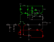
Ive built a low power aleph m of sorts without the active ac current source. using it as a gain stage. when powered up on +/- 45 volt rails it oscillates immediately at @ 1-1.2MHz. Anyone have any ideas what would cause this? please refer to the circuit pictured. using 9610's and 610's for the mosfets. Im using a connex smps power supply but had the same osillation when powered from a filtered transformer.
Attachments
no jfets in the circuit, bjt for the current source and mosfets for everything else. I would like to say a BIG thank you Mr. Pass for taking the time to reply to my question though! can you please give me more insight as to what i should look for? i would say Im a novice still with just enough knowledge to get in trouble, lol.
i can say that when i tried a cap across the feedback resistor it raised the oscillation frequency to @6MHz
What value cap did you try ?
Also, separately, in ref to Nelson's original suggestion - ditch the protection zeners at the input stage and see if that helps.
What value cap did you try ?
Also, separately, in ref to Nelson's original suggestion - ditch the protection zeners at the input stage and see if that helps.
Why would input protection zeners cause oscillation?
Thanks.
The schematic in post#1 appears not to include any frequency compensation, to set the open loop unity gain frequency and the phase margin (!).
There's a 47uF capacitor which determines the low frequency rolloff, and an 1nF capacitor which stabilizes the tight local feedback loop around the current source.
But there aren't any capacitors that create a dominant pole which gives a comfortably large phase margin with plenty of stability cushion, for the amplifier as a whole. None!
Yikes.
i see the A30 link, I dont have what amounts to Q4 in the A30 circuit so do i still need 1nf in that position for stability? Zen Mod are you saying to use like 100 ohm gate resistors throughout?
as I sad - 1nF , in two positions
put them , there is no harm
Zen Mod, if i dont have what amounts to q4 in the a30 diagram would i just connect 1nf to virtual ground between the feedback resistor and the output? Again thank you to all who are taking the time to help me out. so if i understand correctly adding resistance to the gate stoppers effectively slows down how fast we can turn on and off the mosfets? I should have considered that, thanks! how high could one go without slowing the amp down to much to affect the audible range with the gate capacitance of the 610's? learning this stuff is addictive....
well , I can't explain better than it's already shown on schematic
Q4 is having nothing with that lower 1nF , which is connected from output mosfet gate (prior to gate resistor , which you can observe as internal part of mosfet itself) to appropriate node ..... so 1nF is taming mosfet's gate , not Q4
increase mosfet gate resistors from present value until you get amplifier instead of oscillator
say that 470 , even 680R aren't critical in your case , but better to start from lower value - 270 or 330R
besides that - try to use some logic in feedback resistors values** - observe Aleph 30
**series resistor and resistor to gnd on input side need to be similar to same resistors on inner side of LTP
that's basic electronic ........ which you need to know prior to mindless Lego chaos-ing
been there ........ for too long ...... so believe me , major benefit is in learning
If original circuit uses IRFP240 and now you have IRF610, change gate resistors immediately.
You may need to go as high as 2kohm...
Gradually, until oscillation stops.
That's probably it.

just wanted to say thanks to everyone that helped me here. added the other 1nf cap and bypassed the feedback resistor with 10pf cap. I didnt change the gate resistors since now I have a clean waveform. Im sure adding resistance to the gate stoppers would help more but i sleep better at night knowing i havent slowed the amplifier down.....
THANK YOU!
THANK YOU!
- Status
- This old topic is closed. If you want to reopen this topic, contact a moderator using the "Report Post" button.
- Home
- Amplifiers
- Pass Labs
- Please help diagnose bad oscillation