If you read Nelson's article on power supplies ( http://www.passlabs.com/pdf/powersupply.pdf ), he goes for 3x the power draw:
I am quite confident you would be fine with 750VA. If I had 1000VA toroids I'd be completely happy - more doesn't hurt here")
My reason for raising this issue is more for budget minded constructors looking at purchasing toroids, or ordering them custom made. The additional cost of 1000VA cf 750VA in $$$/weight/size isn't to be ignored.
cheers, mark
However, prior to this he uses the term "several times" and other sources I have read suggest 2x as an acceptable minimum, which is what I stated.If the stereo amplifier is rated 200 watts per channel pure Class A, it will draw about 1000 watts all the time, meaning that about 3000 watts of power transformer is called for, no less.
I am quite confident you would be fine with 750VA. If I had 1000VA toroids I'd be completely happy - more doesn't hurt here
My reason for raising this issue is more for budget minded constructors looking at purchasing toroids, or ordering them custom made. The additional cost of 1000VA cf 750VA in $$$/weight/size isn't to be ignored.
cheers, mark
Part of the trick here is that transformers with a higher VA rating will be designed with bigger gauge wire to source more current, so as a result, the series resistance will be lower. This, in turn, will give your supply better voltage regulation. You want to minimize the transformers series resistance to minimize your IxIxR losses which are equal to the voltage drop across the tranformers secondaries.
The lower your final rail voltage, the more important this becomes, because you have less voltage to spare. A 2V drop with 50V rails is <5% which is acceptable. The same 2V drop on the Aleph 3 25V rails is nearly 10% which can start to be a problem.
Rodd Yamashita
The lower your final rail voltage, the more important this becomes, because you have less voltage to spare. A 2V drop with 50V rails is <5% which is acceptable. The same 2V drop on the Aleph 3 25V rails is nearly 10% which can start to be a problem.
Rodd Yamashita
I got the quote from R-Theta for the 24 heatsinks required to realize my cassing. 8.54$CND each (US$5.70...if buying 25) plus 25$CND (US$16.67) setup charges. This will be expensive but acceptable since they suit my specifications.
I found out that R-Theta have a sale office 15 km from where I live...I would have saved a lot on shipping if it would have the factory.
regards,
Gabriel
I found out that R-Theta have a sale office 15 km from where I live...I would have saved a lot on shipping if it would have the factory.
regards,
Gabriel
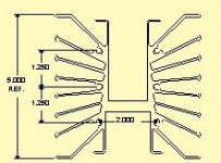
I am building a pair of Aleph 2's and have gotten back a very reasonable quote form M&M Metals. Thought I would post it here and see what you guys thought. The MM5060 is almost cheaper new than to go with Surplus sinks. I am going to use the MM5060 Heatsink and there will be 6 per Amplifier(3 down each side). 2 Devices per sink. It will give the amp a sort of industrial look to it.
"Price for 12 parts of MM5060 is 17.39 each."
"Price for 4 parts of MM5047 is 118.92 each."
"Delivery in 2 to 3 weeks."
http://www.mmmetals.com/pages/extruded high & medium/high/high_power_extruded_page.htm
Although I have not done any calculations yet I feel that 6 of these per amp should out work nicely. Any feedback here would be appreciated and thanks in advance.
Mark
Could you gents please post that in laymans terms? I'm definately not an angineering type guy.....
Here is a link to the M&M Specs. Scroll about half way down.
http://www.mmmetals.com/pages/extrusion profiles/extrusion tables/center web & box & shelf.htm
Thanks!
Mark
Here is a link to the M&M Specs. Scroll about half way down.
http://www.mmmetals.com/pages/extrusion profiles/extrusion tables/center web & box & shelf.htm
Thanks!
Mark
Jan:
The heatsink requirement is 0.1 °K/W per channel. Mark is planning on using 6 pieces which means that each piece needs to have maximum 6 times the requirement in order to meet the requirement as a set. That is 0.6 °K/W which divided by 6 for total for the 6 pieces is 0.1 °K/W. I think you misunderstood (I know you know this stuf WAY better than I).
Mark:
Without getting into detail about insulation and other things and what it does to hotspots and junction temperature:
A heatsink is rated for a temperature increase in degrees (Kelvin or Centigrade) per watt it is asked to dissipate. If a heatsink is rated at 1 °K/W (or 1 °C/W for that matter) that means that the heatsink will have it's temperature increased by 1 degree for each watt led into it. Consequently it will increase it's temperature by 10 degress for 10 W (it is not quite linear but for this discussion we pretend it is). Now, if we use two of those heatsinks rated at 1 °K/W then they will dissipate half of the power each, effectively meaning that they get 5 W each giving a 5 degree increase acting is they were one heatsink at double the capacity (HALF the rating) of the individual. (Mathematically this is kind of like resistor in parallell sharing the current between them, two 1 ohm resistors in parallell makes 0.5 ohm i.e. two 1 °K/W heatsinks make one 0.5 °K/W heatsink).
Taking 6 heatsinks the same type means that the total temperature resistance (which it is called) is one sixth of that for the individual piece. So, if you need 0.1 °K/W and you have a bunch of 0.6 °K/W heatsinks you would need 6 of those to get what you need.
The above replies from Jan and William could be somewhat confusing as William started from the requirement and gave you what was need for each piece if you were to use 6 of them. The anwer is 0.6 °K/W as William said (remember 0.6 per piece giving 0.6/6 °K/W = 0.1 °K/W). Jan assumed that you were talking 0.1 °K/W sinks (which would be PRETTY big) which in his calculations gives 0.1/6 °K/W = 0.17 °K/W. Both are correct calculations but William gave you what is needed per piece and Jan described a dream for all of us (?).
I DO apologise for the lengthy answer
/UrSv
Read more: http://www.aavidthermalloy.com/technical/index.shtml
Aavid 400860
http://www.aavidthermalloy.com/products/index.shtml
is more space efficent and has the same *C/W as the MM5060.
It will also be much easier to mount the transistors and reduce wiring lengths. It also looks nice.
http://www.aavidthermalloy.com/products/index.shtml
is more space efficent and has the same *C/W as the MM5060.
It will also be much easier to mount the transistors and reduce wiring lengths. It also looks nice.
While they may reduce wiring lengths by a bit they would be so expensive as to not be practical. These guys won't talk small quantities. Good luck.......and so on. I've already tried Thermalloy and Wakefield. Bah!
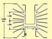
Fortunately I have access to a verticle mill so I could do a similar thing with the M&M heat sink and mill the back so its just flat, and for only 12 bucks! Also mounting the transistors on the M&M won't be difficult at all and the wire lengths can still be kept to a minimum by mounting the 2 TO-247P's to the center flat of the heatsink and the PCB to the side wall. That way there shouldn't be much more wiring than if I had hand wired on two large flat back heat sinks.
As far as the look goes who would say the Krell KSA-80 was a bad looking amp. I thought its looks made a great statement about the capabilities of the amp as a whole. Ditto for the Threshold series that had massive side sinks. Just don't trip and fall into em. Ouch......
Mark
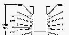
"If the back is milled flat then ......."
Mark,
By the above quote, do you mean:
1. Cut off the few fins on the bottom (as seen by the picture from your post) and then install screws via the top and bottom chassis plate?
2. Or you mean install screws from the top and bottom chassis plate and thus the bottom few fins will be hiding under the top chassis cover plate?
3. Either way, is it rigid enough to withstand rough handling? Say, somebody pick up the amp using the heatsink as a handle? I know this sounds like a worst case but you never know. Or you have some other forms of bracing?
I have always wondered how one would install this shape of heatsink since they looks good and they are not necessary very expensive.
Jag,
I don't mean to offend anybody but the approach that you just posted seems to be the "previous style" of doing things. From everything that I've read so far on this forum, it appears that people are building amps or pre-amp with the guts inside the chassis and only exposing the heatsinks. Peter Daniel influence?! My guess is that Mark is also approaching it from the "present style" of building things and I'm also interested in how he go about doing it.
I don't mean to offend anybody but the approach that you just posted seems to be the "previous style" of doing things. From everything that I've read so far on this forum, it appears that people are building amps or pre-amp with the guts inside the chassis and only exposing the heatsinks. Peter Daniel influence?! My guess is that Mark is also approaching it from the "present style" of building things and I'm also interested in how he go about doing it.
As to Marks heat sinks I wouldn't mill the ends, too much work and you loose dissipation.
They have mounting holes on ends and you use them for bolting sinks to chassis wall. If the wall is at least 1/4" thick you can easily lift the amp by the sinks and nothing will brake (maybe your back only ). It would be the best to mount fets on the sink and use short pieces of wire as an extension. I built Zen amp using similar heatsinks before and it worked great.
They have mounting holes on ends and you use them for bolting sinks to chassis wall. If the wall is at least 1/4" thick you can easily lift the amp by the sinks and nothing will brake (maybe your back only
). It would be the best to mount fets on the sink and use short pieces of wire as an extension. I built Zen amp using similar heatsinks before and it worked great.- Status
- This old topic is closed. If you want to reopen this topic, contact a moderator using the "Report Post" button.
- Home
- Amplifiers
- Pass Labs
- The perfect heatsink