Hi All
I am thinking about building an experimental amplifier employing a Super Triode Connection (STC) with a Zen amp + Aleph CCS. The STC was discussed rather in detailed in some Japanese audio website and also in TubeCAD. Employing the concept laid out in TubeCAD around mid 2015, I combined a Zen Amp (with Aleph CCS) and draw up the schematics. The working point that I selected was based on the components available in my parts inventory. I would like to ask the help from the forum to see if there are obvious miss in the thought before attempting to build one. Thanks.
I am thinking about building an experimental amplifier employing a Super Triode Connection (STC) with a Zen amp + Aleph CCS. The STC was discussed rather in detailed in some Japanese audio website and also in TubeCAD. Employing the concept laid out in TubeCAD around mid 2015, I combined a Zen Amp (with Aleph CCS) and draw up the schematics. The working point that I selected was based on the components available in my parts inventory. I would like to ask the help from the forum to see if there are obvious miss in the thought before attempting to build one. Thanks.
Attachments
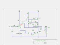
Zen Mod, you hit the right spot. I do not understand this also, hence I call it an experimental build. Nevertheless the claims made by the concept are so attractive that I am willing to spend the effort to experiment.
According to the claims, the triode is NOT part of the gain stage, but an active feedback element. With this Super Triode Connection (STC), you get the sound characteristics of the triode but the power of the main amplifier. So in my case, I can get a E88CC (or 6DJ8) sound-like power amplifier. This is very interesting.
I basically share the concepts shown in TubeCAD
Single-Ended Amplifiers & Super-Triodes and so on in building the schematics. Also, there is even a commercial offering using a gainclone with a tube:
Nixiekits.eu • Finest quality Nixie clock and tube kits made in Germany
Why?it could be supertriode amp , if you didn't omit entire biasing circuit for lower mosfet
this way , all you could get is poof! in speaker
 I believe FYC took the schematic from art_zv2.pdf. I think some of us would need a bit more explanation. Is it because he used 47k instead of 4k7? But I just can't figure that as valid cause for a poof!
as Mr. Broski said cleverly:
and then he put this picture :
so , find that part on page , read and think
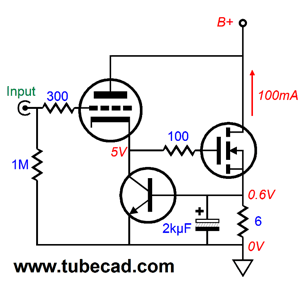
Wait a minute, John; what happens if the triode's cathode voltage isn't high enough to turn on the MOSFET; or too high, so the MOSFET over conducts and melts?
The answer is we need an auto-bias circuit to set the MOSFET's idle current flow, such as the one shown below.
and then he put this picture :
so , find that part on page , read and think
maybe because still didn't get my morning coffee , but I can't see how's that going to work
I see the logic of it - the Mosfet is driven by a Triode Cathode follower, and
negative feedback is provided by connecting the output (Mosfet Drain) to
the Plate and working the Triode characteristic of the tube.
Mr. Pass, does this means the biasing change is still usable?I see the logic of it - ...
I see the logic of it - the Mosfet is driven by a Triode Cathode follower, and
negative feedback is provided by connecting the output (Mosfet Drain) to
the Plate and working the Triode characteristic of the tube.
I know these schmtcs from Broskie (entire page ) , what struck me in the early morning is fact that tiny details about biasing elements can't be omitted without bigbadaboom consequences , except if just basic schm. is in case
which isn't declared in post #1

now , I can draw working schematic , needing some optimizing of triode loading , but why should I ...... when almost everything is already shown in TubeCAD blog
as Mr. Broski said cleverly:
and then he put this picture :
so , find that part on page , read and think
Yes, you want the picture below it, and even then it would not be my choice...
Agreed...., but that's an exercise for the designer.

- Status
- This old topic is closed. If you want to reopen this topic, contact a moderator using the "Report Post" button.
- Home
- Amplifiers
- Pass Labs
- Super Triode Connected Aleph CCS Zen Amp