Hi Everyone,
After a couple of years with no diy audio activity, I'm starting up a new project. Two or three years ago, while still living in Brazil, I started collecting parts to rebuild my F5; I liked the one I had built (original design, not turbo), but I thought I could do better with more care. Now I'm a bit more organised after moving in Maine I've decided to get moving and get it done. I have a pair of Peter Daniel's PCBs, a pair of 250VA toroidals, and various parts I can reuse from the old build, so the plan was (and is) a pair of monoblocks. Although I liked the heatsinks on the old build they were just a little too small, so I've bought four E008 sinks from HeatsinkUSA - which should be more than sufficient if I use two for each monoblock.
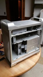
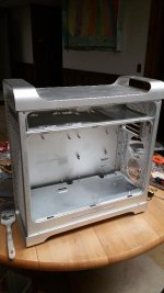
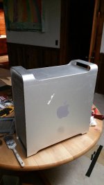
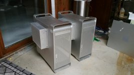
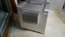
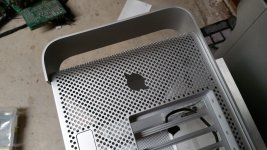
There is loads of information on this site on how to build an F5. The reason for a new thread is an idea I had for the chassis that I thought might be of interest to other people planning a Pass amp build, or anything similar. Rather than building a pair of chassis from scratch, I got a hold of some old Apple G5 computers that the university was sending for recycling. These are pretty heavy and very well made; entirely anodized aluminium, 1/8 inch mostly, with a little steel, and are extensively ventilated. On closer examination they have several other properties that are handy for repurposing them for amps; the power supply is in the bottom of the chassis (unlike the newer Pro models, where it is at the top) and is separated from the rest of the case with a steel sheet, so the trafo can be put there, and is screened form the rest of the circuitry. There is another steel shelf near the top, so any other circuitry like speaker protection circuits (or anything else, really) could be put up there if you want. There are also convenient (and well-designed) fan slots if you need/want them, although I don't intend to use them. Last, there is an excellent lever-action system for taking the side-panel off, which is very convenient for tweaking things later.
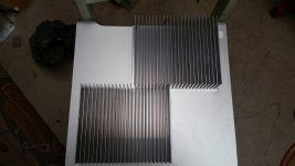
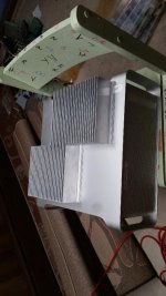
I'm attaching some photos of the how it looks with everything removed. Also a slight conundrum: the heatsinks are just a little too wide to fit side-by-side on the side of the cabinet, and I am reluctant to cut them, since I might want to use the cabinets one day for a larger amp build (F5 turbo or something else, who knows?). Anyone have thoughts on putting them as shown, one higher than the other but overlapping? Seems to me it would work well; it would mean mounting the pcbs with one mosfet vertically above the other, one on each sink, rather than placed horizontally, but that doesn't seem such a big deal.
I'd be interested to hear any comments, or any success/failure stories from people who have tried similar things. I'll post updates as things progress.
Nigel
After a couple of years with no diy audio activity, I'm starting up a new project. Two or three years ago, while still living in Brazil, I started collecting parts to rebuild my F5; I liked the one I had built (original design, not turbo), but I thought I could do better with more care. Now I'm a bit more organised after moving in Maine I've decided to get moving and get it done. I have a pair of Peter Daniel's PCBs, a pair of 250VA toroidals, and various parts I can reuse from the old build, so the plan was (and is) a pair of monoblocks. Although I liked the heatsinks on the old build they were just a little too small, so I've bought four E008 sinks from HeatsinkUSA - which should be more than sufficient if I use two for each monoblock.
There is loads of information on this site on how to build an F5. The reason for a new thread is an idea I had for the chassis that I thought might be of interest to other people planning a Pass amp build, or anything similar. Rather than building a pair of chassis from scratch, I got a hold of some old Apple G5 computers that the university was sending for recycling. These are pretty heavy and very well made; entirely anodized aluminium, 1/8 inch mostly, with a little steel, and are extensively ventilated. On closer examination they have several other properties that are handy for repurposing them for amps; the power supply is in the bottom of the chassis (unlike the newer Pro models, where it is at the top) and is separated from the rest of the case with a steel sheet, so the trafo can be put there, and is screened form the rest of the circuitry. There is another steel shelf near the top, so any other circuitry like speaker protection circuits (or anything else, really) could be put up there if you want. There are also convenient (and well-designed) fan slots if you need/want them, although I don't intend to use them. Last, there is an excellent lever-action system for taking the side-panel off, which is very convenient for tweaking things later.
I'm attaching some photos of the how it looks with everything removed. Also a slight conundrum: the heatsinks are just a little too wide to fit side-by-side on the side of the cabinet, and I am reluctant to cut them, since I might want to use the cabinets one day for a larger amp build (F5 turbo or something else, who knows?). Anyone have thoughts on putting them as shown, one higher than the other but overlapping? Seems to me it would work well; it would mean mounting the pcbs with one mosfet vertically above the other, one on each sink, rather than placed horizontally, but that doesn't seem such a big deal.
I'd be interested to hear any comments, or any success/failure stories from people who have tried similar things. I'll post updates as things progress.
Nigel
Attachments

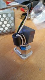
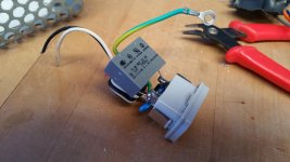
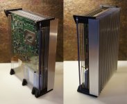
The power socket on the power supply of the G5 has a heat-shrinked filter arrangement on it. I cut one open (since I thought the wires were a little too thin) so here's what's inside. The Y2 capacitor across the mains is 1uF, which seems high, although there are two other components which look like caps from live and neutral to earth, so maybe that affects things in some way. The ferrite is handy, and I expect to use it, with a 0.0033uF cap as in the original design and slightly heavier wires. Does anyone know for sure what the blue components are? The only marks I can read say CS102M so maybe they're Y class caps of some kind? Any point in keeping them?
Of course, a G5 computer pulls plenty of current, and this arrangement must be safe enough, so anyone who wants to can presumably use it without pulling the heatshrink off...
Of course, a G5 computer pulls plenty of current, and this arrangement must be safe enough, so anyone who wants to can presumably use it without pulling the heatshrink off...
Attachments
I saw the heading and said "This I gotta see".
Congratulations, enjoy the result.

Thanks, Nelson. Of course, I have to actually *finish* them first...
2 of this sinks pr ch is overkill in a standar F5 (it looks as it is 10.080" profiles and about 8" long) you can do it with only 1 sink pr ch. I use 2 of this sinks (6" long) pr ch on my F5 with standar PSU voltage and 2.6A bias and 2 output pairs. and it stays at about 55C with 25C ambient temp.
you can do it with only 1 sink pr ch. I use 2 of this sinks (6" long) pr ch on my F5 with standar PSU voltage and 2.6A bias and 2 output pairs. and it stays at about 55C with 25C ambient temp.how about using the heatsinks internally, and using low speed fans to pass the air from front to back?
This is definitely a possibility which I considered. The design of these computers is very clever, and it looks like the plastic fittings that hold the fans can easily be replaced (more or less) after building an amp in the empty chassis, and putting fans in later would be simple if they are needed. I've heard that the original fans are noisy, although I haven't tried them, so you may want to change them for quieter ones of the same size. If you're going to use fans together with internal heatsinks, then another interesting possibility might be to find a way to use the (impressive!) heatpipe heatsinks that are on the processors in the G5. I thought about this, and may try it in the future; however I've also got a pair of (slightly) newer Apple computers with a different internal layout and different heatsinks that look like they might be a better choice than the G5 for this purpose.
For this build I'm going to stick with external heatsinks, mostly so that I have more space inside to experiment later; for instance, if I want to change to a CLC filter on the power supply then I'll probably need plenty of space.
Nigel
As above, surprised to see passive sinks glued to the case exterior.
Necessary? there are 3 100 mm? fans inbuilt and one could easily upgrade those in both CFM and Silence. Lotsa market/product available for PC cooling. Air or Water
One can also buy 'cheaply' (80$) Antec Cases (comes to mind example only) that are designed for 6 100 /140 mm fans. All of which are sub 20db gizmos.
Only real issue is that a PC case can be a largish rascal
Last edited:
This project is asking for fan assisted heatsinks inside the case and some sound proofing on the chassis!!
With a tunnel heatsinks and 120mm computer fans you should be able to reach really good dissipation with really low noise, below 10db.
As above, surprised to see passive sinks glued to the case exterior.
Necessary? there are 3 100 mm? fans inbuilt and one could easily upgrade those in both CFM and Silence. Lotsa market/product available for PC cooling.
I agree there are good ways to do this with internal heatsinks and fans, and I considered it. I'm going to stick with the external heatsinks for this build, although if I had thought of using these cases before I bought the big heatsinks I might have done things differently.
2 of this sinks pr ch is overkill in a standar F5 (it looks as it is 10.080" profiles and about 8" long)
Yes, they are 10.08" profiles, and are 8" long. I may have overengineered the design a bit (it's a habit...
) buying two per channel. The original idea was to use one on each side of each monoblock, as part of the design; the idea of repurposing these cases made that more complicated.I've wondered about using only one on each monoblock. If I think about it I can probably build with one per channel and reconfigure things to use two if necessary. (Or just for the hell of it, to see what difference it makes...) Also, since the case itself is anodised aluminium it will presumably help a bit in dissipation also.
Of course, I have to actually *finish* them first...
Mere details. The idea is the thing. Maybe you can use some PC heat sinks.
Mere details. The idea is the thing. Maybe you can use some PC heat sinks.
PC heatsinks are a great idea.. some of the larger ones can dissipate 200w, and fabricating a thick copper plate that attaches to it will allow more devices per heatsink. Otherwise watercooling could be an option.
I'd suggest heat-sinks inside to.
I have probably a half-dozen of these (with who knows how many more coming no doubt). They can be oriented in any of 3 ways… if you orient it with the front up (you'd need to add footers) you can increase colling effectiveness with convectional tunnel cooling.
1st build for me will be a dual mono, Allen Wright inspired PP EL84, tubes sticking out the top. I have about 12' of 8"x8" ½" wall square tube i plan on chopping up for class A monobloks.
dave
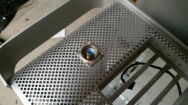
I've mounted the heatsinks on the cases, bolted through the flanges and the side of the case. Later I'll cut holes for the mosfets to be mounted directly on the heatsinks. For the present I'm just using one sink on each case - if I need more for any reason (like scaling up to a F5 turbo, or who knows what) then there's space to put more sink on. It looks to me like anyone who would like to build a stereo amp in one of these cases could mount a similar sink on the other side, although possibly the latching mechanism would need a little reinforcing.
The perforated backs of the cases also made it a simple matter to mount RCA sockets, or anything else. (I've chosen Neutrik sockets, as shown.) Enlarging some of the holes and a few minutes with a file took care of it.
I measured the blue caps in the photo in post 2 - they measure as 17pF, although my capacitance meter may not be very reliable. Nobody responded to my earlier query about keeping them. If I use a 0.0033uF X2 as in the F5 article, is there any reason to keep these blue Y caps?
Attachments
Why not use a full-size heat sink ?
If you worry about too much heat sinking, you can always reduce the fin depth.
Patrick
.
Hi Patrick,
That is a beautiful computer in your photo.
I didn't explain all the reasoning for choosing only one heatsink, but the main reasons boiled down to simplicity. Mounting one heatsink as bought is a simple matter, and can be tried first with little trouble and no burned boats. On the other hand a wider or full-width sink would be much more complicated, so I thought to go that route only if necessary. (I dropped the idea of using two whole sinks in the odd placement I showed above.)
Of course, your post now has me thinking that over again. If I cut a third heatsink in two I can make heatsinks 15" long by somehow joining a whole and a half sink together. This would be shorter than the case by a couple of inches at each end. To make a sink that is exactly as long as the case would mean cutting two heatsinks, one for each case. The cuts would then have to be milled (or filed) and either the two pieces fixed to the case very precisely so that the join looks good, or the two pieces would have to be attached to each other before fixing to the case. In the first case I would need to find a good way to clamp everything together very carefully before drilling, and then tap several dead-end holes in the sinks. This is certainly doable, but there isn't much margin for error. An alternative would be to get a friend's help and weld the two heatsink pieces together before fixing to the case. I know nothing about welding, and little about using a milling machine, but I'm told it can be done. (As can milling some of the fins off later, if necessary, as you suggest.)
But what would the advantages be to doing this now? Arguably the cases would look nicer with full-length sinks (although there's no way they'll look as elegant as your computer), but is there any other reason for doing these now? Why not wait and see if one sink is enough?
A lot of useful suggestions, but at the end of the day you have a plan and want to use what you have on hand. So, just do it--the way you want to! DIY is DIFY.
Here is my DIY Audio theme song
https://www.youtube.com/watch?v=9SXWX6qg0y4
- Status
- This old topic is closed. If you want to reopen this topic, contact a moderator using the "Report Post" button.
- Home
- Amplifiers
- Pass Labs
- Building F5 monoblocks in Apple G5 cases