Hello,
I'm building an A40 and would like to use crc filtering in the power supply. I'm wondering if using a 30-0-30 650 VA X-Former would be OK as the no load voltage would be about +-42 volts DC which is 10 over the orginal specs. I'm figuring about 5 volts will be lost to bridge, caps, resistors etc. Bringing the rails down to around +- 38. Thanks in advance for your input.
I'm building an A40 and would like to use crc filtering in the power supply. I'm wondering if using a 30-0-30 650 VA X-Former would be OK as the no load voltage would be about +-42 volts DC which is 10 over the orginal specs. I'm figuring about 5 volts will be lost to bridge, caps, resistors etc. Bringing the rails down to around +- 38. Thanks in advance for your input.
Their no need to use a CRC in the supply it will only decrease the performance of the power supply. Also, 650w is a minimum a 1Kw would be much better.
I have built several of these amps and using a 650W transformer the DC will droop or sag from the load. You can run these amps from +/-30V to +/-45V dc with no problem.
I also have some of extra Lamda output transistors.
I have built several of these amps and using a 650W transformer the DC will droop or sag from the load. You can run these amps from +/-30V to +/-45V dc with no problem.
I also have some of extra Lamda output transistors.
jewilson said:Their no need to use a CRC in the supply it will only decrease the performance of the power supply.
I don't think so. Not in classA amps.
grataku,
Anytime you add resistance in the supplies lead it's burn up energy and increases the impedance of the supply. Ideally, you want the supply impedance to be as close to zero over the frequency range. If you run a FFT with either resistors or inductors you will find that slew rate under load can be effected, even in class A.
Another way to look at this is hang a resistive load in series with the speaker, does that sound like a good thing to do? Well you could add a .5 ohm but going higher would not be cool.
In a tube amps you can get away with doing this since the device are not low impedance and are voltage devices.
Next, why do this the amp work great as Nelson designed it, with out resistor in series with the supply.
If you want to change something the amp sound better with match FETs and some source degeneration.
")
Anytime you add resistance in the supplies lead it's burn up energy and increases the impedance of the supply. Ideally, you want the supply impedance to be as close to zero over the frequency range. If you run a FFT with either resistors or inductors you will find that slew rate under load can be effected, even in class A.
Another way to look at this is hang a resistive load in series with the speaker, does that sound like a good thing to do? Well you could add a .5 ohm but going higher would not be cool.
In a tube amps you can get away with doing this since the device are not low impedance and are voltage devices.
Next, why do this the amp work great as Nelson designed it, with out resistor in series with the supply.
If you want to change something the amp sound better with match FETs and some source degeneration.
jewilson said:grataku,
If you want to change something the amp sound better with match FETs and some source degeneration.
FETs????? You haven't built the A40 I see..... BJT's all the way!
I have built several of them using +/-45 V, and have never had problems with it. All you do is make the amp have more watts in class AB. Mine were able to give out 450 W bridged in 4 ohm with a 1KVA trafo. I used one of these for each selfmade Apoge (Lafolia presented in the Danich magazine High-Fidelity) copy for a long time with good results (except for burning tweeters a few times).
All you have to take care of is the voltage accross the current source.
For bass these amps are marvelous!
I'm using the one I have left for highs now, while I'm waiting to finich my Alep-X amps (I HAVE cards
). 
Anders
Anders, Yes I have built several of them. there nothing special about making this change and their nothing special about the small transistor used in the design.
You can repalce just the differential pair, which are the input transistors. There no need to replace other components. The part I used was a 2N5566 which is the same part Nelson used in the 2nd run of the Threshold amps. You should also add some source degeneration about 100 ohm should work fine on each source.
Work great Try it
You can repalce just the differential pair, which are the input transistors. There no need to replace other components. The part I used was a 2N5566 which is the same part Nelson used in the 2nd run of the Threshold amps. You should also add some source degeneration about 100 ohm should work fine on each source.
Work great
Try it2n5248
Quote: You can repalce just the differential pair, which are the input transistors. There no need to replace other components. The part I used was a 2N5566 which is the same part Nelson used in the 2nd run of the Threshold amps. You should also add some source degeneration about 100 ohm should work fine on each source.
Jim,
Can you recommend a replacement for the 2n5248?
A40 Driving 4 Ohm Load
Mr. Pass,
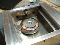
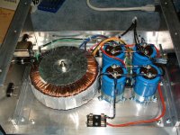
I'm working on an A40 and would like to use it to drive a small pair of maggies. As I'm sure you know they are 4 ohms of almost pure resistance. An amplifier could not ask for a nicer less efficient load. What steps could I take to optimize the A40's operation into this load? I'm going to use an 800va transformer 30-0-30 and 50 to 100K of filtering per rail. I'm thinking that each device would have to be biased at about 1.5 amps. This would mean lots-o-heat. Could I add another pair of ouch puts to each side to further distribute the current across each pair? Thanks in advance for your help!
Mr. Pass,
I'm working on an A40 and would like to use it to drive a small pair of maggies. As I'm sure you know they are 4 ohms of almost pure resistance. An amplifier could not ask for a nicer less efficient load. What steps could I take to optimize the A40's operation into this load? I'm going to use an 800va transformer 30-0-30 and 50 to 100K of filtering per rail. I'm thinking that each device would have to be biased at about 1.5 amps. This would mean lots-o-heat. Could I add another pair of ouch puts to each side to further distribute the current across each pair? Thanks in advance for your help!
Regarding the 2N5248 FET used as a current source in the A40, the part is hard to find and may not be adequate for voltages above 40V. It can be simply replaced by a 22K resistor from ground to the bottom of R9, with slightly reduced power supply rejection ratio.
While the original used +-32 volts, the design scales nicely to slightly higher voltages (with suitable part changes). Substituting 2N5401s for the PNPs and 2N5551s for the NPNs will suffice in the front end, but the VAS and its current source may need to become higher dissipation parts for above 40v (or decrease the VAS current by changing R10 to 150 ohms).
I don't recommend integrated Darlingtons for the outputs, since it is hard to find them with the recommended 25 ohm base-emitter resistors built in. You need to make your own from discretes. You will run into safe operating area constraints as you increase power out and voltage, and may need more devices in parallel as power output rises and possibly go to a cascode output stage.
Regarding the 2N5248 FET used as a current source in the A40, the part is hard to find and may not be adequate for voltages above 40V. It can be simply replaced by a 22K resistor from ground to the bottom of R9, with slightly reduced power supply rejection ratio.
There are a number of different FET's that can be use here since it just used as a current source. You should check the idss and the gate to source breakdown voltage which need to be around 40-50 VDC if you running with a +/-40 supply. What ever FET you use, check the leads. I have seen FETs with the same part number where the leads are swapped.
If you use the Lambda Transistors in the outputs this will work. I do have extra ones. The A40 amps I have built all run at +/-32 volts and it get quite warm, that what mine were built with a fan.
the a40 kicks
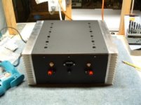
just spent the evening listening to my A40
ti is still screwed down to a board no enclosure yet.
the sound well, compared to my hafler dh220
it is astounding! I knew the hafler was a piece of crap,
but not that bad
yhe advice on heatsinks is right with the ouputs(2n6051&2n6058) mounted on hafler dh200 heatsinks run at 75c
owe thats not gonna work

was using a signal 80-6 so output was a little low
so final version will use a signal 120-8
all other transistors are 2n5551 and 2n5401
need a higher voltage jfet for the ccs
any suggestions
just spent the evening listening to my A40
ti is still screwed down to a board no enclosure yet.
the sound well, compared to my hafler dh220
it is astounding! I knew the hafler was a piece of crap,
but not that bad
yhe advice on heatsinks is right with the ouputs(2n6051&2n6058) mounted on hafler dh200 heatsinks run at 75c
owe thats not gonna work
was using a signal 80-6 so output was a little low
so final version will use a signal 120-8
all other transistors are 2n5551 and 2n5401
need a higher voltage jfet for the ccs
any suggestions
- Status
- This old topic is closed. If you want to reopen this topic, contact a moderator using the "Report Post" button.
- Home
- Amplifiers
- Pass Labs
- A40 Rail Voltage