I just noticed that the PSU schematics shown in Nelson Pass' original texts on the F5 and the F5-Turbo are somewhat different (see attachments), and I wonder why.
What are the advantages and disadvantages of each set up?
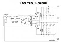
- The F5 document shows one secondary of the transformer connected to the rectifier bridge of the positive rail, and the other secondary connected to the rectifier bride negative rail. The secondaries are not connected to GND.
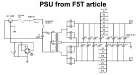
- The F5-Turbo document shows each secondary connected to half of the rectifier bridges of each rail. The secondaries are connected to GND.
What are the advantages and disadvantages of each set up?
Attachments
dual graetz setup is good as preventing any DC in secondaries , which is sort of inevitable in sole graetz iteration , as result of possible DC imbalance in circuit
when there is no imbalance , these two are practically the same
What do you mean by "dual graetz" vs. "single graetz"? (F5 = single / F5T = dual? Or the other way round?)
And I don't really understand how imbalance in the circuit may cause DC across the secondaries. Can you give me a hint (or example)?
there are two ways to wire up a dual polarity supply.
Dual secondaries to dual rectifiers to dual smoothing caps and finally connected at the output. The F5 example uses this type.
or
Centre Tapped secondary to single rectfier to series connected smoothng capacitors. The F5T uses this type.
There is no significant difference between them.
a.) There is a small decrease in output voltage from the dual secondary/dual rectifier type.
b.) There is a small change in the way the hum+noise appears on the DC output.
With my crude measurements I cannot measure that second (b) difference, but some other Members claim it affects their sound quality.
I can easily measure the voltage loss of the first (a).
I note that the F5T diagram now uses a power rectifier across the Power Thermistor in the Chassis to Power Ground Disconnecting Network.
Did Pass draw this? Or is this an invention from one of our Members in the light of my comments about the F5 thermistor alone not being reported as tested?
Last edited:
Forget he mentioned "imbalance".What do you mean by "dual graetz" vs. "single graetz"? (F5 = single / F5T = dual? Or the other way round?)
And I don't really understand how imbalance in the circuit may cause DC across the secondaries. Can you give me a hint (or example)?
I too don't understand "graetz".
I too don't understand "graetz".
"Today the circuit is still often referred as Graetz circuit or Graetz bridge"
https://en.wikipedia.org/wiki/Diode_bridge
What is the reason for the difference?
One uses 35A monolithic bridge rectifiers.
The other uses discrete 35A diodes that share a cathode. The displayed schematic uses 4 to generate both rails.
You can use 8 of them to make a dual bridge rectifier, without any issues apart from the lower output voltage.
Ok, well. I just finalised the design for my F5T PSU and sent the PCB design out for production (I'll use a CLC PSU with 50'000 uF -> 1 mH / 0.3 Ohm -> 50'000 uF per rail / monoblock). I just used the "F5 set up" for this, since I didn't realize the difference in the F5T schematic. Should I care? Will this spoil my F5T?
(I don't think so, but I need some emotional support by the Gurus).
I just copied the drawings from the PDF documents available from firstwatt.com, so I guess the drawings were made by Nelson Pass.
(I don't think so, but I need some emotional support by the Gurus).
I note that the F5T diagram now uses a power rectifier across the Power Thermistor in the Chassis to Power Ground Disconnecting Network.
Did Pass draw this? Or is this an invention from one of our Members in the light of my comments about the F5 thermistor alone not being reported as tested?
I just copied the drawings from the PDF documents available from firstwatt.com, so I guess the drawings were made by Nelson Pass.
- Status
- This old topic is closed. If you want to reopen this topic, contact a moderator using the "Report Post" button.
- Home
- Amplifiers
- Pass Labs
- PSU difference between F5 and F5T (connections of secondaries)