wuffwaff said:Hi Terry,
an oscillating amp can´t sound very well...... You still have the problem of R1/4 being very hot wich means that you´ve got a problem here. Try to put the scope on these and see what waveform you have.
This maybe is also the cause for your transformer running hot.
Try upping the C´s in the active current source from 3n3 to 6n8 or more. Maybe the bogger input capacitance of the fets you use has an influence here.
William
For some reason I used 7pF for C9 and C10. I don't remember now where I came up with that value. Where is it stated what value that should be? I looked through the wiki and I didn't see it.
I'll try something different there.
Bessings, Terry
Hi William,
Yeah they were 7 +/- .5pf 500VEM. I bought them thinking I needed 5-10pf. I figured they fit right in there.
I didn't have any 4n7's handy but I did have some 3n3's so I put those in both channels. I'll pick up some 4n7's this week. I also changed out all of the 0r15 resistors for 0r22 on one channel only so I could test the difference. The channel with the 0r22's sounds more muffled than the other. A little less presence in the upper mids and treble. This was not an improvement in sound to my ears.
The channel with the 0r22's had to be biased at .530v on the source resistors in order to get the offset right. If I set it at .5v the offset would go to about 200mv. With them at .530 the offset is about 72mV. That's with the absolute offset at around +/-5mV.
Oh yeah, I also changed the input caps to 12uf orange drops in bothe channels. That's as close as I could find locally.
Well, I don't know how to measure output but here's what I tried.
I fed a 440hz sine wave into both channels one at a time by using one audio feed and moving it from channel to channel. I measured AC voltage across the + and - outputs. I had a pair of 4ohm speakers plugged into the speaker jacks, one each side.
The channel with the 0r22 source resistors measured higher. I then hooked up the scope and hooked one probe each to the + and - outputs, set it to inv and add, and set the waveform to just touch two lines on the scale. Then I switched channels and they were almost identical in strength. If this is a dumb test, please let me know so I won't keep doing it.
OK on another note, after about an hour and a half, the heatsink on the channel with the 0r22 resistors is at 51c. The other is at 60c.
Oh yeah, I changed the resistors in one channel of the PSU to a pair of 0r22 25w resistors per rail. This is the same channel that got the other changes. I'm reading a drop across those of 0.570VDC at a rail voltage of 14.75VDC. The channel with the 0r15 source resistors still has a pair of 0r1 5w resistors per side and I'm reading 0.356VDC drop across them with a 14.6VDC rail.
I guess that's enough rambling for now. Still looking for suggestions.
Thanks, Terry
Just a small update. I switched peakers and found that the speakers had more of an affect on the sound than the amp. Reversing the speakers revealed that the channel with the 0r22 resistors doesn't sound more muffled. That was coming from the speakers. Probably more placement than anything but still, I wanted to make that clear. The two channels sound almost identical.
I'm beginning to warm up to the sound of this amp. It seems to have it's own charm.
I believe I'll change out the other channel's resistors too. I like the lower heat.
Blessings, Terry
I'm beginning to warm up to the sound of this amp. It seems to have it's own charm.
I believe I'll change out the other channel's resistors too. I like the lower heat.
Blessings, Terry
GRollins said:Mark,
Choose the resistor value according to how much bias you want and how much heat you can safely dissipate. Lower resistor values (all things being equal, meaning you don't fiddle the current source, etc.) will, of course, lead to higher bias current. Look at your speaker load impedance and decide what its minimum value is. Work backwards from there, then throw in a bit of extra bias, just for spice.
5 1/2 digits will do fine for matching. What tolerance are the Vishays? 1%? I wouldn't even bother matching them, myself, but then I'm short on time. Someone with more time on their hands might feel that tweaking the R values would be worthwhile.
Grey
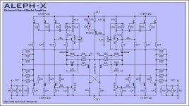
Grey,I have an other question,I want to build hight power verions aleph-x with 100W power output,but I can not get the 0.47Ohm resistor for A-X,so I plan use 2pcs 1ohm parallel connection,1ohm//1ohm=0.5ohm to replace the all 0.47Ohm resister in attached schematic.Can it work well and steady?thanks
Leo
Attachments
still4given said:Hi William,
... Oh yeah, I also changed the input caps to 12uf orange drops in bothe channels. That's as close as I could find locally.
... OK on another note, after about an hour and a half, the heatsink on the channel with the 0r22 resistors is at 51c. The other is at 60c.
Oh yeah, I changed the resistors in one channel of the PSU to a pair of 0r22 25w resistors per rail. This is the same channel that got the other changes. I'm reading a drop across those of 0.570VDC at a rail voltage of 14.75VDC. The channel with the 0r15 source resistors still has a pair of 0r1 5w resistors per side and I'm reading 0.356VDC drop across them with a 14.6VDC rail.
I guess that's enough rambling for now. Still looking for suggestions.
Thanks, Terry
The orange drops are OK - did you notice an improvement in the sound when you got rid of the electros?
Increasig the source resistors reduced the bias current, resulting in less heat. Looks like 0R22 is right for those heat sinks.
How is the psu ripple voltage and no signal output trace on the changed channel? Your bias there is about 5.5A, which would show reduced ripple, (measure AC on the rails) and your increased R in the CRC woulod further decrease the ripple.
Are your R1 and R4 still getting hot? Did you souble check their value? I can't tell you how many times I have typed the wrong value into my mouser order (6.8R meaning 68, etc.)
How warm is your transformer with the reduced load?
BobEllis said:
The orange drops are OK - did you notice an improvement in the sound when you got rid of the electros?
Increasing the source resistors reduced the bias current, resulting in less heat. Looks like 0R22 is right for those heat sinks.
How is the psu ripple voltage and no signal output trace on the changed channel? Your bias there is about 5.5A, which would show reduced ripple, (measure AC on the rails) and your increased R in the CRC woulod further decrease the ripple.
Are your R1 and R4 still getting hot? Did you double check their value? I can't tell you how many times I have typed the wrong value into my mouser order (6.8R meaning 68, etc.)
How warm is your transformer with the reduced load?
Hi Bob,
I really couldn't hear any difference. Perhaps if I did them one channel at a time and compared I could have, but I changed them all at once. My memory is not good enough to tell you if there was much difference.
The AC voltage is reduced with the pair of 0r22 resistors in the power supply. I read only 24mV of AC after the filters. If I lower the scope enough I can see a small ripple on the scope but I don't think it is hurting anything.
R1/R4 are not hot as long as I keep the absolute offset low. This is like chasing your tail though. Everytime I check the absolute offset it is different. I will get it settled down and then check it a half and hour later and it will be back to a volt or two +/-. Even so, at a couple of volts, R1/R4 won't be very warm. When I first start the amp cold the absolute offset might be close to rail voltage. As it warms up it drops. Very weird! Relative offset is more stable. I have about 70mv offset on the channel with the 0r22 source resistors. Probably because I didn't take the time to match them. When I matched the 0r15's originally they were all very, very close. I'm using Dale 1%. I will match the rest before I put them in the other channel. If it looks like I need to, I will pull these and match them. From what I've read, 70mV is OK.
I listened to the amp for a couple of hours last night through my nearfields. It sounds quite nice through them. I don't know if I'm missing anything yet. I will do more comparisons once I get the case all put back together, and get it off of my bench. I'll let it be my listening amp for a while. I still need to finish up my second KSA50. The AX will be what I listen to while I work on that. By the end of that, I should know if it's a keeper or not. It might end up in the master bedroom as a space heater.

Blessings, Terry
Hi
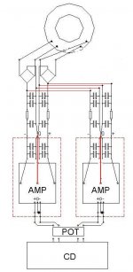
I have AlephX connected as show on the picture. The problem is that when I trim DC offset on one channel it have influence on the other channel. If I connect only one channel I have DC offset of about 20-50mV but when I connect booth of them it rise to 120mV.Now when it rise to 120mV I cant lower it to 0mV, as if I lower DC offset on one channel it rises on the other, so the best I can do is ~120-150mV on booth channels. Is it normal ?
I have AlephX connected as show on the picture. The problem is that when I trim DC offset on one channel it have influence on the other channel. If I connect only one channel I have DC offset of about 20-50mV but when I connect booth of them it rise to 120mV.Now when it rise to 120mV I cant lower it to 0mV, as if I lower DC offset on one channel it rises on the other, so the best I can do is ~120-150mV on booth channels. Is it normal ?
Attachments
BobEllis said:Terry,
Glad you have a listenable amp. Is the fuzziness you mentioned earlier gone? that could have been the electros if it wasn't an oscillation issue.
Hi Bob,
Yes the fizzle seems to be gone. It may have been the electros though I think it stopped before I changed them. I'm going to have to give it some time. It seems a little light in the bass right now. Could be that I'm being too critical right now. Someone earlier said the output devices I used may be influencing the sound. I may never know. Then again, if I can't warm up to the sound, I may try replacing them in the future. Now that I've lowered the bias, the IR's should work, should I chose to change them. I'd love to hook up a spectrum analizer some time and see if my ears are telling me the truth. The amp sounds better through my Event 20/20 nearfields than it does through my big JBL's. I'll try it a few different ways over the next couple of weeks and see how it feels. At least I can touch it now.
Thanks for all you kind help in getting this amp working. It's folks like you who make this hobby such a joy to be part of.
Blessings, Terry
yoke said:Hi
I have AlephX connected as show on the picture. The problem is that when I trim DC offset on one channel it have influence on the other channel. If I connect only one channel I have DC offset of about 20-50mV but when I connect booth of them it rise to 120mV.Now when it rise to 120mV I cant lower it to 0mV, as if I lower DC offset on one channel it rises on the other, so the best I can do is ~120-150mV on booth channels. Is it normal ?
Hi,
did you use any input caps on the X? I don´t see them in your drawing and they are needed.
BTW are you speaking of absolute or relative dc-offset?
William
Hi William,
Why do you say that the input caps are needed?
I am building Aleph-X monoblocks and I am not currently planning on using input caps. The original Aleph-X schematic does not include them. I also remember that NP said that if the preamp output was capacitor coupled and you were sure that no DC was coming into the Aleph-X that input coupling caps were not required.
Thank you
Graeme
wuffwaff said:
Hi,
did you use any input caps on the X? I don´t see them in your drawing and they are needed.
BTW are you speaking of absolute or relative dc-offset?
William
First I didn't use it. I use only from - to 0 since I drive this unbalanced. When I notice that DC offset off one amplifier have influence on the other I place 4.7uF BG NX on input + but it didn't help. Nothing has changed so no meter if I use input capacitor or not.
I am speaking about difference betwin + and - on speaker output.
The offset from output + or - to ground is from 1 to 5V when I connect bouth chanels...when I have only one connected i think it's around 1V.
Yoke,
make shure you use the same type of cap for +IN and -IN and connect -IN to ground through this cap for unbalanced use.
Using the amp with an X-BOSOZ will lead to dc variation since the output is not really dc-coupled (look at the feedback resistors to the gate).
Graeme,
that is true if your source is realy free of dc and you use it balanced. BTW the commercial AX amps also use input caps.
William
NP and William,
Thank you for your posts.
William,
Pass Labs amplifiers are AC coupled on the input because the company can't be certain whether the customers pre-amp has DC on the output or not. This makes good sense.
However, you state that the input coupling caps are still necessary if you drive the amp unbalanced. I don't know that I would agree. I would agree that it is easier to pick up offset problems between equipment due to grounding issues etc when you use unbalanced connections rather than balanced ones.
I would sum up by saying that I agree that having these caps in place is good insurance. I am just trying to avoid the physical bulk of adding 5+ uf film caps to my amplifiers.
Thanks again.
Graeme
Graeme,
I never tried the amp without input caps after reading Peter Daniels reports quite a long time ago.
When you use unbalanced dc-coupled connections you will load both inputs differently.
Since I wanted to mate it to an X-BOSOZ wich has a small amount of dc-output depending on the input (thanks to the X-resistors wich are dc-coupled) I never further investigated.
William
- Home
- Amplifiers
- Pass Labs
- Aleph-X builder's thread.