Ok getting somewhere today. I have settled on values 2n2 for C9/10 and 1n0 for the ones on Q4 and Q9. Amp powers up from cold unstable and gets stable within the first 12 seconds (when offset drops below +5VDC).
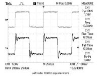
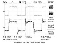
Did some measurements today and I'm still concerned. Firstly I have severe ringing on 10kHz square waves. It drops significantly with an 8ohm load connected across the amp, but as shown in the attached pictures both a single side of the amp, and the summed components of -ve and +ve ring at around 125kHz. This is with a 3pf or 5pf cap in the feedback loop, I can't remember and will play with this tomorrow.
But on the bode plot I found my amp is resonant at exactly 114kHz. Using a baseline of 1kHz it's reasonably flat. At 20kHz we're at +0.2dB and this keeps rising to a +2.9dB at 114kHz around the same frequency as my uncompensated amp oscillations . Above the 114kHz it drops quite dramatically with a -3dB point at 220kHz at 12dB per octave.
Is this second order response normal for this amp design? I get the feeling that playing with the capacitance just masks the problem. Is there another way to dampen the response of the amp or am I overthinking this?
Did some measurements today and I'm still concerned. Firstly I have severe ringing on 10kHz square waves. It drops significantly with an 8ohm load connected across the amp, but as shown in the attached pictures both a single side of the amp, and the summed components of -ve and +ve ring at around 125kHz. This is with a 3pf or 5pf cap in the feedback loop, I can't remember and will play with this tomorrow.
But on the bode plot I found my amp is resonant at exactly 114kHz. Using a baseline of 1kHz it's reasonably flat. At 20kHz we're at +0.2dB and this keeps rising to a +2.9dB at 114kHz around the same frequency as my uncompensated amp oscillations
. Above the 114kHz it drops quite dramatically with a -3dB point at 220kHz at 12dB per octave.Is this second order response normal for this amp design? I get the feeling that playing with the capacitance just masks the problem. Is there another way to dampen the response of the amp or am I overthinking this?
Attachments
48 or 52
you'll not hear diff between that two
I realise that, but I have been considering raising it to 66% as my speakers have quite a low impedance. Need to know if I"m going the right way.
Interesting, I've heard the sound is worse but you make it sound like it will be actually quite bad. Some people have built 66% amps before. Anyway I'll take your word for it, don't need all that power in 4ohm anyway
In case anyone is interested I have got a rock solid amp now and have settled on the following values: C9/10: 2n2, Q4/9 caps: 1n0, C2/4: 12p
Amp has a bandwidth of 180kHz, and a nearly critically damped square wave response.
For reference in case anyone else has stability issues I've attached bode plots and square wave responses measured for changes in various capacitors on the amp. May help someone along in the future. File format is MS Excel .xlsx
Now to go match the same parts on the left channel.
Attachments
OK, ignore my previous post. It looks like if I use a 1.8uF cap, this will provide me with a 2.2Hz high pass filter (I was trying to save some money). I've read through Tony's capacitor test and found the same reference to using a 0.01uF Vishay MKP1837 polypropylene as a bypass. These are cheap enough - I'll grab a dozen or so...
I'll be very surprised if you like the 1837 as a bypass. What about sonicap?
Pass DIY Addict
Joined 2000
Paid Member
Hmmm... I've used the original Gen I Sonicaps in small pair of bookshelf speakers I made about 10 years ago and they sound nice in that function. My intent to was experiment with some of the "higher end" caps and thus I was exploring Mundorf and Audyn - there seems to be universally high praise for these...
Which line of Soincaps were your thinking?
Which line of Soincaps were your thinking?
Hi guys , looking for some help here as i bought a pair of aleph X monoblocks few yrs ago but did not use it until now. One of the block is working fine relative Dc offset is 10-20mV and absolute dc offset is 150mV. My problem is the other monoblock. From what i can see it is home brew pcb based on original Grey's version ie 15V ,biased at 0.5V, 4 mosfets each chanel, no input caps, no output resistors to ground. The problem is that relative dc offset is about 7V, absolute dc offset from positive to ground is 1.2V but 9V measured from negative output to ground. The voltages across 392ohm resistors are 0.4V and 0.42V respectively. I was able to adjust the absolute offset close to zero but it quickly drift off. Sorry i don't understand much regard amplifier circuit and not sure where to start checking or measuring to work out what to do next.I tried to measured the input diferential irf 9610 but could not make head or tail about it. Would a failed irf 9610 explained the high relative dc off set?
Thank you
Quan.
Thank you
Quan.
Hey folks,
I've done some searching on BJT inputs for the Aleph X but haven't seen anything definitive. Is there a standard way to make this upgrade? I have some matched 2SJ170/2SJ74's lying around that I was hoping to use but I don't understand the full scope of the modification. If it's too hard, I'll just stick with the stock configuration but if it's not so hard to do now, I'll just go ahead and implement from the outset.
Thanks!
Hi,
there must be a few schematics in this thread using single and double pairs of fets.
I´ve used a single pair, had to change the bias, the resistor after the fet (from 592R to something around 900R), the McMillan resistors.
DC offset can be set with a pot 10R or 20R that also fuction as a pair of source resistors. This makes matching a bit easier.
Amp has been like this for a few years now. Works fine.
Here´s the thread:
http://www.diyaudio.com/forums/pass-labs/98763-alephj-x.html
William
Here is the most recently posted schematic for the AX100J's that I built. Note that this project pre-dates the Aleph J and the X'ing of that circuit and slightly post-dates Williams work.
http://www.diyaudio.com/forums/pass-labs/73543-ax100-100w-aleph-x-monoblocks-46.html#post1468122
The JFET's each run 5ma of bias to duplicate the 10ma through the original MOSFET's. This means no tinkering with other circuit values. Tinkering is to be avoided with the Aleph X. The transconductance with the JFET's is lower than with the MOSFET's. However there is still enough OL gain to keep things good.
I eventually removed the 15 ohm JFET source resistors.
Here is a comment from Nelson on the topic.
http://www.diyaudio.com/forums/pass-labs/73543-ax100-100w-aleph-x-monoblocks-37.html#post1404305
Graeme
Thanks for that! Can I use just one pair of the 2sj74 (matched) in this case? And I assume I still want to make sure they are thermally coupled? Do they require heat sinking as the 9610s do? I think I read about people gluing them together and some fancy custom sinks for a pair.
The 2JS74's will work fine. If you use my schematic you will need 4 per channel to replace the two 2SJ109's I used.
I did not match the 2SJ109's to each other in each channel. I just used one half of each on each side of the diff pair and relied on the cascodes to keep any current hogging from getting bad. It seems to be working. Maybe I just got lucky pulling the parts out of the bag. If I did this over again I would use matched 2SJ74's instead. Popular opinion says a 10% match is good enough.
Some people thermally connect the transistors together. It can't hurt and I do it when it's easy to do. For four TO-92's running 5ma each with 8V across them I probably wouldn't bother. The Aleph-X has a lot more DC offset stuff going on so you probably wouldn't see the benefit of thermal tracking in actual use.
Graeme
Last edited:
Hrm... I'm still thinking about the jfet upgrade. I realize that it would be easier to have the conversation with the schematic but didn't know if it was bad form to ask for help while using boards from Jim's audio. I bought them from a fellow diyaudio member who is supportive of this website. I myself have also donated and am a proud "aficionado."
Sorry for the off-topic question... perhaps a moderator can clear this up without having too much back and forth on what has likely sucked up too much of peoples' time and energy previously.
Sorry for the off-topic question... perhaps a moderator can clear this up without having too much back and forth on what has likely sucked up too much of peoples' time and energy previously.
- Home
- Amplifiers
- Pass Labs
- Aleph-X builder's thread.