alepx
Hi I'm making me a alepx, but the surprise has been that we have tried entering the RCA and only gives 30 watts of power,
We know you have to go balanced but may provide 100 watts to Balak (is a stage should go qeu balanced)
I would appreciate please indicate if it is normal
thanks
Hi I'm making me a alepx, but the surprise has been that we have tried entering the RCA and only gives 30 watts of power,
We know you have to go balanced but may provide 100 watts to Balak (is a stage should go qeu balanced)
I would appreciate please indicate if it is normal
thanks
Aleph-X PCB's
Hi members,
I am looking for PCB's for the Aleph-X amplifier.
I need 3 amplifiers so I would like to buy the PCB necessary.
Thanks ,Victor")
did you ground neg. input , while giving unbalanced input ?
if everything is OK , that's just matter of needed greater input swing
Hi members,
I am looking for PCB's for the Aleph-X amplifier.
I need 3 amplifiers so I would like to buy the PCB necessary.
Thanks ,Victor
Pass DIY Addict
Joined 2000
Paid Member
Aleph-X input cap type and value?
After living with my Aleph-X amps for some time now, I've become interested in upgrading my input caps.
Currently, I'm using Dayton Metalized Polypropylene 4.7uF caps (from PartsExpress) and R18/R19 are each 10kohms. If I measure across the XLR- and XLR+ input pins with my meter, I get an input impedance of about 38.7kohms.
Using the formula f=1/2*Pi*R*C, it looks like a 0.47uF cap will give me an 8Hz high pass filter, which should be fine.
So, after hours of reading, I've narrowed things down to 3 possibilities for the type of cap I should use: Intertechnik Audyn Cap True Copper MKP for about $25 each, Mundorf Silver/Gold/Oil for about $60 each, and Clarity Cap MR MKP for about $38 each.
Am I unncessarily splitting hairs here, or will these three caps largely be indistinguishable from one another as compared to the Daytons that I am currently using?
Also, the Mundorf caps seem to have an upper temperature of 55c. This seems to be a bit too close for comfort to use inside my Aleph-X chassis.
Should I just go for the Audyn Cap as a lower cost option?
Last edited:

Pass DIY Addict
Joined 2000
Paid Member
Pass DIY Addict
Joined 2000
Paid Member
OK, ignore my previous post. It looks like if I use a 1.8uF cap, this will provide me with a 2.2Hz high pass filter (I was trying to save some money). I've read through Tony's capacitor test and found the same reference to using a 0.01uF Vishay MKP1837 polypropylene as a bypass. These are cheap enough - I'll grab a dozen or so...
Pass DIY Addict
Joined 2000
Paid Member
While poking around trying to learn more about input caps for amp, I found this interesting link that provides some background on corner frequencies and phase shifts associated with input caps.
Hi All, I'm finally at the end of the line. I built some Aleph-X amps a while ago and have been battling getting them going for months. The main problem was stability and for a while an inability to bias the amp. Finally put bias problems down to a dead C5 cap. Anyway I'm now 90% there and I'm out of ideas battling my instability issues.
Basically my amp most closely resembles Eric's running about 8A a side with +/-20V rails. The basics of the amp work, as in nothing is bursting into flame and a small input signal is amplified, power supplies are stable, it's drawing the correct current, and I have 11mA going down the input pair.
The problem I am having is oscillations and absolute DC offset, and the two are related. Here's what I've seen so far:
- I power up my amp with V2 set to zero and the amp oscillates at a messy 180kHz + 230kHz. Changing V2 does nothing to the stability. Absolute DC Offset starts at around -2VDC and heads south to around -11VDC.
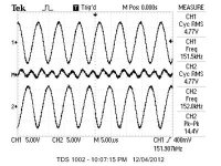
- I added a 1n C9 and C10 and now when I turn on I get reasonably clean looking oscillation at 150kHz at each channel. However after the amp heats up and the Absolute DC Offset gets below -7.5VDC the oscillations appear again.
- I upped C9 / C10 to 3n3 and now I can get the offset down to -3VDC with lots of tweaking of V2 before the oscillations appear again. Of note is that the amp seems to start up with a higher Absolute Offset now, so from cold start it still seems to take 1+ minute to stabilise.
And now I'm here with the perplexing question. Am I destined to just battle the oscillation by upping C9/10 until the amp has an unhealthily anorexic bandwidth? Or can someone hint at what I'm doing wrong? Schematic and scope capture of bandwidth attached.
Basically my amp most closely resembles Eric's running about 8A a side with +/-20V rails. The basics of the amp work, as in nothing is bursting into flame and a small input signal is amplified, power supplies are stable, it's drawing the correct current, and I have 11mA going down the input pair.
The problem I am having is oscillations and absolute DC offset, and the two are related. Here's what I've seen so far:
- I power up my amp with V2 set to zero and the amp oscillates at a messy 180kHz + 230kHz. Changing V2 does nothing to the stability. Absolute DC Offset starts at around -2VDC and heads south to around -11VDC.
- I added a 1n C9 and C10 and now when I turn on I get reasonably clean looking oscillation at 150kHz at each channel. However after the amp heats up and the Absolute DC Offset gets below -7.5VDC the oscillations appear again.
- I upped C9 / C10 to 3n3 and now I can get the offset down to -3VDC with lots of tweaking of V2 before the oscillations appear again. Of note is that the amp seems to start up with a higher Absolute Offset now, so from cold start it still seems to take 1+ minute to stabilise.
And now I'm here with the perplexing question. Am I destined to just battle the oscillation by upping C9/10 until the amp has an unhealthily anorexic bandwidth? Or can someone hint at what I'm doing wrong? Schematic and scope capture of bandwidth attached.
Attachments
Pass DIY Addict
Joined 2000
Paid Member
After checking the differential pair (measure approx 4v across R23 and R25) as Zen points out, my next thought is that you don't have DC offset (V2) adjusted properly. You say that oscillations begin when DC offset hits -7.5v. Try adjusting V2 so that offset starts high (more like positive 7-10v). As the amps warms up over 30-45 mins, it offset should drift toward zero. Keep adjusting until absolute offset stays at zero when the amp is warm. This should cause high offset when the amp is cold. It sounds like you don't have any oscillation problems when offset stays closer to zero volts...
Hi,
normally you should set the absolute DC offset when warm. Cold offset is what it is and depends on the used zener and McMillan resistors. In my Aleph-X it starts up at around +8V.
C9/10 are around 3n3 or 4n7 in my amp (there must be a thread where everything is written down)
Did you use wirewounds as source resistors?
Do you have input caps installed as I can´t see them on the shematic?
Hope this helps,
William
William
Definitely adjust the DC offset to zero after warm up, as William says.
Another way to tame oscillations is to increase the gate stopper resistors on the output MOSFETs. This will help to limit the bandwidth.
Your output gain stage with IRFP044 has about twice the transconductance of an output stage with IRFP240 with a similar number of FETs. My guess is this the cause of the oscillation. Larger source resistors could help. That's just a guess; someone else should weigh in on this point.
Looking at your schematic, it isn't clear how you wired the parallel sets of output transistors. For example, R8 should only connect to the source of Q1 (and not Q3/Q5/Q7). Similarly, R10 should only connect to Q2 (not Q4/Q6/Q8). You probably wired the output stage correctly, but if not, this certainly could cause instability.
Jeremy
Wow I'm amazed at the quick responses.
Zen, pictures coming soon, no camera here at the moment. And yes 11mA through each of the input stage. Measured 22.1mA out of the front end source.
Eric, oscillations start as my amp APPROACHES zero volts absolute offset. At -7VDC it becomes stable.
Wuffwaff, I've got 2x 1ohm low inductance wirewound resistors on each source. No input caps installed currently, but I did try with them, and connected to a preamp with output caps, and currently inputs shorted to ground with no change in offset or response. Interesting that you needed 4n7 caps to get your amp stable? Maybe I'm overreacting given how I've read most people haven't needed them and it's just a feature of my choice of parts.
kropf, sorry I mocked up that schematic to keep track of the parts I'm playing with. The amp is wired up as per Blitz's 100w schematic except with 8x IRFP044 a side rather than 6. Sense line is only connected to the first MOSFET in each group. Do I understand your post correctly that the increase in number of MOSFETs also contributes to potential instability as does the choice of IRFP044 over the 244? So maybe with my choice of parts I just need to reduce the bandwidth with caps and all is good then? Times like these I wish that my analogue design lecturer spoke fluent english.
I've actually gone brute force and added 4n7 to C9/C10, and 1n5 to the caps on Q4 and Q9 collectors to the output. That has stabilised the amp. I was under the impression that this is a bandaid for a mistake I made, but the more I read the more I think my amp just needs it for stability, and that the values aren't so uncommon. Certainly the additional caps are in the Aleph30 schematic. Is there any major sonic issue with setting the amp up with these caps?
Anyway with the thing stable I twiddled V2 and now have my offset issues sorted as well.
Eric, I have another problem. Firstly thanks for the wonderful website. It is what made me want to build the things a few years ago and it's inspiring to see you're still maintaining it. Currently I'm doing some measurements and trying to figure out the AC current gain. I noticed your website now has a banner saying something doesn't match what others are seeing. Can you share what you think may be wrong?
Following your instructions with my amp I've come to an AC current gain of 88% I'm getting the following readings using 100Hz at about .3Vp-p input since my dummy load is only 25watt:
R12 = 1k3 (same as yours)
R2 = 6x 0r47 = 78.3mV = 1A
R5 = 2x 1r = 60.3mV = 120mA
now do I multiply my R5 current by 4 since I have 4 MOSFETs? That's not entirely clear to me. If I don't which is what I am assuming reading your website I get 88%. If I do then I get 52% which makes more sense, and if it's correct may be a nice thing to mention on the site.
Cheers, all
Zen, pictures coming soon, no camera here at the moment. And yes 11mA through each of the input stage. Measured 22.1mA out of the front end source.
Eric, oscillations start as my amp APPROACHES zero volts absolute offset. At -7VDC it becomes stable.
Wuffwaff, I've got 2x 1ohm low inductance wirewound resistors on each source. No input caps installed currently, but I did try with them, and connected to a preamp with output caps, and currently inputs shorted to ground with no change in offset or response. Interesting that you needed 4n7 caps to get your amp stable? Maybe I'm overreacting given how I've read most people haven't needed them and it's just a feature of my choice of parts.
kropf, sorry I mocked up that schematic to keep track of the parts I'm playing with. The amp is wired up as per Blitz's 100w schematic except with 8x IRFP044 a side rather than 6. Sense line is only connected to the first MOSFET in each group. Do I understand your post correctly that the increase in number of MOSFETs also contributes to potential instability as does the choice of IRFP044 over the 244? So maybe with my choice of parts I just need to reduce the bandwidth with caps and all is good then? Times like these I wish that my analogue design lecturer spoke fluent english
. I've actually gone brute force and added 4n7 to C9/C10, and 1n5 to the caps on Q4 and Q9 collectors to the output. That has stabilised the amp. I was under the impression that this is a bandaid for a mistake I made, but the more I read the more I think my amp just needs it for stability, and that the values aren't so uncommon. Certainly the additional caps are in the Aleph30 schematic. Is there any major sonic issue with setting the amp up with these caps?
Anyway with the thing stable I twiddled V2 and now have my offset issues sorted as well.
Eric, I have another problem. Firstly thanks for the wonderful website. It is what made me want to build the things a few years ago and it's inspiring to see you're still maintaining it. Currently I'm doing some measurements and trying to figure out the AC current gain. I noticed your website now has a banner saying something doesn't match what others are seeing. Can you share what you think may be wrong?
Following your instructions with my amp I've come to an AC current gain of 88%
I'm getting the following readings using 100Hz at about .3Vp-p input since my dummy load is only 25watt:R12 = 1k3 (same as yours)
R2 = 6x 0r47 = 78.3mV = 1A
R5 = 2x 1r = 60.3mV = 120mA
now do I multiply my R5 current by 4 since I have 4 MOSFETs? That's not entirely clear to me. If I don't which is what I am assuming reading your website I get 88%. If I do then I get 52% which makes more sense, and if it's correct may be a nice thing to mention on the site
.Cheers, all
Pass DIY Addict
Joined 2000
Paid Member
Garbz,
Sorry, my misunderstanding about offset as voltages approach zero...
I've been updating my web page for the past 10 years. I'm afraid the length of the document reflects this timeline. As for AC current gain, I haven't looked at this section in a few years to try to figure things out. When I followed what others indicated on my first time through, my results were somehow backwards - thus when I thought I was increasing ac current gain, it was actually decreasing ... But I haven't figured out where my math went wrong. I would follow William's assessment here.
Garbz said:Wow I'm amazed at the quick responses.
Do I understand your post correctly that the increase in number of MOSFETs also contributes to potential instability as does the choice of IRFP044 over the 244?
I've actually gone brute force and added 4n7 to C9/C10, and 1n5 to the caps on Q4 and Q9 collectors to the output. That has stabilised the amp.
It was just an idea (too high transconductance = instability), but it is at least a reasonable idea. I don't have practical experience or even a simulation that shows it to be a problem. With 16 IRFP240s and the hifizen boards, I had no stability problems, but it's been years since I looked and I have made several changes since.
Looking back to your orignal post, you say you have a bias current of 8A per side. That's a whopping huge amplifier! Wow! But it brings up another possibility for instability, especially since adding caps to Q4/Q9 solved the problem. 8A per side would be 2A per MOSFET and with 50% AC current gain you get 4A peak. The current limiters will definitely kick in and create distortion at high output levels. The 100R/221R at the base of Q4/Q9 divides the signal at R6, which peaks at 2V (0.5R x 4A). The bases of Q4/Q9 could see 0.62V, which is high enough to steal current from the gate of Q2/Q11 for high signal levels. Check the voltage at the base of Q4/Q9 with no signal. It should be less than 0.25V. If it is more, change the voltage divider to reduce the base voltage.
Jeremy

you need the contribution of the current source which seems to be 4x120mA so 480mA of 1000mA which is 48%.....
Is it 48% or 52%? The wiki leads me to believe the formula is 1- (480/1000)*100 which makes it 52%
- Home
- Amplifiers
- Pass Labs
- Aleph-X builder's thread.