Sander,
Would suggest higher voltage devices - lower junction capacitance for MBR range - cheap, tho.
Match up the diodes, too, as sometime large variation.
Suggest avoid common mounting bolt/brackets thru the 2 txr, and max seperation - it's okay to sit them flat - better with 1 txr, despite the BS.
Nice, short wiring.
jameshillj said:Sander,
Would suggest higher voltage devices - lower junction capacitance for MBR range - cheap, tho.
Match up the diodes, too, as sometime large variation.
Suggest avoid common mounting bolt/brackets thru the 2 txr, and max seperation - it's okay to sit them flat - better with 1 txr, despite the BS.
Nice, short wiring.
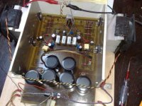
IRF has the MBR1645. Maximum continous current at 16A. 45V rated. The next one is the MBR1050. 10A continous at 50V. I am aiming a 6A bias per channel so the 10A device will almost run it limits.
I wil check the diodes. The Toroid connecting bars are seperated from the chassis by rubber. (bicycle tire
 ) Maybe it is visible on the images. Two small black pieces of rubber between bar and chassis bars. What do you mean by better 1 txr? Isn't a split PS better?
The rectifier diodes are mounted on the small heatsinks in front and at the back.
dr.strangelove3 said:Sander,
Are those the heatsinks that almost set my house on fire?
I can't remember from which member I bought them from. Could be you!
Night owl, eh!
I don't use MBRs so can't say for sure, but would go for the 16A/80+ volt device - but then I tend to go over the top a bit!
As this is an X amp, the txr appears to be less critical, but with my older version,when I relaced the single 500VA with 2 X 300VA torroids it did have "more punch" but not as good image,detail, etc. Then relaced these with a single 450VA EI txr (dual sec) and the amp improved considerably in all respects.
Not a scientific conclusion or anything, and as I've had the same result in the F3 ...
Other folk have different results, apparently.
I was considering upgrading to Rail Regs and other updates but, it's functioning quite well, and is especially good into difficult loads.
I understand that the newer version is a lot clearer, so the Rifa's will emphasize this (such a lot of them, too! Soft-start?)
Okay, first of all thanks to all the people who have taken the time to read through my posts in the Aleph-X thread. I am going to continue posting there only to explore variations on the front end of this amp. All the other measurement, tweak and adjustment posts will be here. Long story short, I think my Aleph-X should be better than it is and I really don't know how to make it better and that is why I'm here.
nania said:\ I think my Aleph-X should be better than it is and I really don't know how to make it better and that is why I'm here.
Nania,
I think you should open your own thread and document exactly what you have built with pcis and a list of everything s we can provide more assistance.
current share/gain
Hi,
Well i've fired the test setup and adjusted them a little. Absolute DC is pretty stable and adjustable (+/- 1 volt). Differential DC offset is wandering about and to much, but that is probably due to poor (no) matching and the way the test setup is constructed (fans and separated heatsinks for the phases). I'll get that solved.
So I'm about to start ordering more and definitive parts. One of those parts are the series ouput and source resistors. That's where i get lost. what does what?
I'm aiming for about 60-65% current gain from the ccs's. Now how to set that. As far as I've understood the ratio between the output series resistors and the source resistors determines the current share with regard to the bias. It does not determine the AC current gain very much, right? AC current gain can be set by altering the ratio between R12 and R8. Is that correct?
so let's say I've got 21V rails and 6A bias, 12 transistors per channel, 0,5R source resistors and 3 parallel 0,27R series resistors per phase. I'm ok as far as current share. I can change the ac current gain by changing r12 right? When I lower r12, gain goes down?
sorry to ask this again. I have searched but I'm not shure and would like some confirmation or correction.
thanks and regards,
Joris
Hi,
to change the ac-current-gain you have to change two resistors I believe it´s R12 and R34.
Lowering them raises the ACG
You could set it as follows:
connect a signal generator and set the output to 3V pp 1kHz into chosen load (or any other value you like)
Measure the ac-voltage over the output resistors an calculate the output current A. (I=V/R)
Measure the ac-voltage over the current-source source resistors and calculate the total ac-current B.
Then you can calculate the ACG
For 65% ACG B/A should be 0,65
Be shure you measuring device can measure at the chosen frequency!
Be shure to listen to 50% too!
William
Hi
Thanks for your answer william. So apart from having the gain change the wrong way round, I've got the concept. The resistors r12 and r34 are the ones to set the AC curren gain with. I'll use the scope and a sound card to fine tune the gain.
As for the 50% gain, it's the reference. I'm listening to it now and it will be the starting point for tweaking the gain. First i'm going to select and order the final parts. Get it to behave like I want to as far as stability and settings and finish it up. only after that I'll start tweaking.
Regards,
Joris
Hello and a late merry xmas to you all,
Yesterday I swapped out the ccs capacitors for some nicer ones and took the opportunity to hook the scope up to all possible circuit positions (previously I only scoped the circuit as a whole). This revealed a 20V AC signal at the bases of Q3 and Q8 (as per Grey's original cicuit) and only there.
Assuming oscillation I tried some capacitance (39pf, it's what i had at hand) from base to collecter around Q3 and Q8, as per the wiki. The only effect this has is to get the same signal on the ouput although at a lower amplitude. I haven't tried capacitance from base to emitter yet or other values as I'm not shure what to look and aim for.
The signal I get is about 20V AC at a time division of 2us, with about two divisions per signal wave ( a distorted square wave or clipped sine, dont know exactly). Sorry, dont know how to translate that to frequency.
Could somebody give me some advice on how to cure this, assuming it is bad? Could it be because of me using bc550 in stead of mpsa18??
regards,
Joris
btw the amps work fine but this is nagging me.
jazz said:Hello and a late merry xmas to you all,
.....
Could somebody give me some advice on how to cure this, assuming it is bad? Could it be because of me using bc550 in stead of mpsa18??
........
did you tried both - 1nF between B&C of Q3 and Q8 , also 1nF between
Q4 C and respective output , same as 1nF between Q9 C and respective output ?
Hi,
Thanks for the advice. I had a look at the parts bin and found some 1n8 and 6n caps. I used the 1n8 base to collector and 6n emitter to collecter. This solved the problem. I'm happy with this for now. In the final build I'll try some different values, go as low as I can and then backup a little for some margin.
Time for some listening and evaluation. piccie of the test setup attached.
Regards,
Joris
Attachments
AX debugging
I have my Aleph-X v1.0 board with J505/9610 CCS (powered from a 3 amp +/-15v bench supply).
At this stage i want to verify that the board is populated correctly and that it's ok to install the power FET's.
For R48 ihave used a wire link and i'm reading 18.8 volts from that link to the negative rail - There is nothing across R23 and R25 has 8.6 volts across it.
R16 has 2.93 volts across it & R30 has 0.03 volts
Q5 has 3v on the gate, Q7 has 0v.
Could anybody point me in the right direction for where i'm going wrong please?
Wolfpako said:hello everybody,
I'am a brandnew member of this amazing forum.
I want to buy two pcbs to built an aleph x amplifier.
There is anyone can help me please.
Many thanks.
I have some rev 1 PCBs that I never built. PM me if you're interested.
Progress
Ok - i found the fault - Q7 was dud.
Afterward replacing Q5/Q7 with a new matched pair i got 4.3v over R23 & R25 and decided to go ahead and connect up the main FET's.
So far so good in that i haven't killed anything yet, but i'm having some trouble adjusting the amplifier.
I'm using a variable PSU capable of 3 amps, but adjusting the bias with V2 is reducing the absolute DC offset but increasing the current draw until the PSU starts current limiting at about 2.8A.
R11 & R33 are changed out for 4k7 instead of 47k5
I'm struggling to get more than about 0.3 over drain resistors R5, 6, 40 & 41.
I'm also not totally convinced about the CCS created by Q6 - i'm only seeing 8.8 volts across a 9.1v Zener, have tried replacing the zener but no difference.
The inputs are floating, the outputs are loaded with a 7R resistor.
Any help would be greatly appreciated.
Current limiting is preventing it coming up correctly
The power supply going into constant current t=rather than constant voltage mode is causing the problem - if i wind Vr1 back far enough to shutoff one of the CS FETs completely then i can get 0.5v on the 0R22 drain resistors on the other other side of the circuit easily - i'll be building another power supply tonight.
I've been a little disappointed at the lack of any kind of response - is the Aleph-X an amplifier that nobody bothers with anymore or is everybody just into other things at the moment?
- Home
- Amplifiers
- Pass Labs
- Aleph-X builder's thread.