Updates
Netlist! You are a genius! Good thing I sent you the pics after all huh?
As far as I can tell the schematic was correct. For the physical connections the left side was correct but the right side was wrong because I forgot that you have to flip the transistors around which switches the source and gate pins. Doh!
OK, so I've updated the pics, for those of you that can get to them they are-
Connection 1 option
Connection 2 option
Connection 3 option
Schematic (left side) (unchanged).
The links are the same so clicking on the prior post will bring up the corrected layouts.
Don't feel bad Bob, its more embarrassing to be the lawyer who made the mistake in the 1st instance!
Anyway I hope these are right.
As Bob says, the connection2 and connection3 options are for placing 3 terminal screw headers onto the board where the transistors were meant to be, which is why the gate resistors on the board are shorted. I thought it might be easier to connect up this way.
Netlist! You are a genius! Good thing I sent you the pics after all huh?
As far as I can tell the schematic was correct. For the physical connections the left side was correct but the right side was wrong because I forgot that you have to flip the transistors around which switches the source and gate pins. Doh!
OK, so I've updated the pics, for those of you that can get to them they are-
Connection 1 option
Connection 2 option
Connection 3 option
Schematic (left side) (unchanged).
The links are the same so clicking on the prior post will bring up the corrected layouts.
BobEllis said:OK - I just looked at the left sides, assumingthat they would be the same. I did the same when LGreen shared the ideas with me privately before posting. Embarrassing mistake for a lawyer to assume rather than verify.

Don't feel bad Bob, its more embarrassing to be the lawyer who made the mistake in the 1st instance!
Anyway I hope these are right.
As Bob says, the connection2 and connection3 options are for placing 3 terminal screw headers onto the board where the transistors were meant to be, which is why the gate resistors on the board are shorted. I thought it might be easier to connect up this way.
moe29 said:don't you just love drilling and tapping?!!
looks great, nice work")
I find drilling and tapping to be really neat but I just don't like doing a lot of holes at once. I broke 1 tap already and had to punch it out with a metal scratch awl. At least that's what I think it is! Tools are not my thing. All those holes on the heatsinks and only 1 that is way far off and about 4 that don't go all the way through (they lined up on a fin).
IXYS bridge
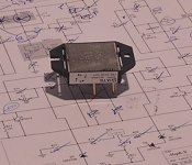
Does anyone know whether the case of the IXYS bridge module VBE 55-06N07 (data sheet here) is isolated or not isolated? Pic attached.
As you see in the pic, the bottom of the package is metal, I've mounted it to my case with thermal compound and it occurred to me that it may be live! I measured it with a DMM and found open circuits between all pins and the case (swapped DMM leads and results are also the same), did a diode test (again swapping leads, same result) and found no drop between any pin and the case.
Funny thing is that IXYS doesn't have any info on this and the data sheet indicates nothing.
Anyone know this package?
I hate to fire up the xformer without being sure.
note- I also posted this question in the krell thread, need a quick answer as this is holding me up....
Attachments
my thoughts...
Hi,
What with my being a newbie, take what I say with caution.
I'd disconnect the DC power leads from the rectifier and then fire it up. Then, measure the case against the two DC output leads with your multimeter. I don't recall using mica with any rectifier.
John
Hi,
What with my being a newbie, take what I say with caution.
I'd disconnect the DC power leads from the rectifier and then fire it up. Then, measure the case against the two DC output leads with your multimeter. I don't recall using mica with any rectifier.
John
good question
Yes, i'm going to fire up mine as soon as my variac arrives next week and reading that part of the wiki left me scratching my head. Please, more instructions on starting this up for the 1st time.
What should one look for when gradually increasing the line voltage? If I could put 2 DMM's and a scope on the circ, what spots should I have them on and what should I see?
Also, I want to check the output mosfets beforehand to make sure they are ok, can this be done with a dmm?
wuffwaff said:Hi,
the only thing you can check is if the current source for the diff pair is working and if the fets are matched properly by looking at the voltages at the 392R resistors.
William
Hi William,
If they are working properly, what's the voltage drop across 392R?
Should I connect to any input when I check it?
Thanks.
Wing
Conrad Heatsinks
Anybody from Scandinavia who's interested in Conrad Heatsinks Group Buy, please take a look at: http://www.diyaudio.com/forums/showthread.php?s=&threadid=74475
Anybody from Scandinavia who's interested in Conrad Heatsinks Group Buy, please take a look at: http://www.diyaudio.com/forums/showthread.php?s=&threadid=74475
again q about keistijan aleph-x
after 140 replies I have chickened a bit idint find info what I need. my 10 pieces aleph-x pcb reaDY TO GO.. except few things.
I am using Kristijan boards, but slightly modified-thicker traces.
http://www.kk-pcb.com/alephx.html
questions
1. I have excelent vishay dale carbon 1% tolerance 10w resistors. 1ohm. if conect 2 in paralel I get 0.50ohm, this is more, original schematic uses 0,47ohm x4 5w is paralel. can I use 8x 10w 1ohm instead originals.
2. bias Left, right and bias q?what values I should use, can i put resitors there, or pot is needed to achieve some voltage points(like in zen v4) if I put pots from waht position start amp? I am sure I will fire first if set pot to incorect value..
what rssitors is the most critical? I used 1% tolerance 0,6w , but they are not the same. irf 240 and irf9610 are mached at 0,01V
my transformers is 18V secondaries.
also Iwant to use one amp on speakers which has 2 ohm impedanse at 70 and 30hzhz . what modification I shopuld do, to make amp that controls loww region well enought.
note I am speaker designer and not a expert on amps, variac, bias etc .
will wait any input..
after 140 replies I have chickened a bit
idint find info what I need. my 10 pieces aleph-x pcb reaDY TO GO.. except few things.I am using Kristijan boards, but slightly modified-thicker traces.
http://www.kk-pcb.com/alephx.html
questions
1. I have excelent vishay dale carbon 1% tolerance 10w resistors. 1ohm. if conect 2 in paralel I get 0.50ohm, this is more, original schematic uses 0,47ohm x4 5w is paralel. can I use 8x 10w 1ohm instead originals.
2. bias Left, right and bias q?what values I should use, can i put resitors there, or pot is needed to achieve some voltage points(like in zen v4) if I put pots from waht position start amp? I am sure I will fire first if set pot to incorect value..
what rssitors is the most critical? I used 1% tolerance 0,6w , but they are not the same. irf 240 and irf9610 are mached at 0,01V
my transformers is 18V secondaries.
also Iwant to use one amp on speakers which has 2 ohm impedanse at 70 and 30hzhz . what modification I shopuld do, to make amp that controls loww region well enought.
note I am speaker designer and not a expert on amps, variac, bias etc .
will wait any input..
PCBs
I can't figure out why no-one is sharing their board designs for this project. Its a very simple board, took me less than an our to draw, so i'm willing to share it if anyone is interested. Unfortunately, my traxmaker won't prind to adobe, so the files are still in traxmaker format... Let me know if you are interested. I made boards for 4 channels with press and peel blue, and it all worked out to less than $20.
I can't figure out why no-one is sharing their board designs for this project. Its a very simple board, took me less than an our to draw, so i'm willing to share it if anyone is interested. Unfortunately, my traxmaker won't prind to adobe, so the files are still in traxmaker format... Let me know if you are interested. I made boards for 4 channels with press and peel blue, and it all worked out to less than $20.
The only thing you can check is if the current source for the diff pair is working and if the fets are matched properly by looking at the voltages at the 392R resistors
Hi Wuffwaff,
isnt it easier to use 392 ohm resistor on one leg, and a pot on the other to get the voltage across the resistors equal?
cheers Arthur
- Home
- Amplifiers
- Pass Labs
- Aleph-X builder's thread.