How to put Aleph-X to work
Hi everyone...It's been a while since I read this tread so maybe someone else answer this question before but...
Whell am thinking of fireing up one channel of my Aleph-X ... I have connect everything so I only nead to pot some AC and hope for the best...
But before I have one question...
I have read wiki page about Aleph-X and here is what it says about fireing up:
4.7.1 - Adjusting the Variable Constant Current Source
Put a 1.5k pot in place of R12/R34.
Connect an 8-ohm ‘dummy’ load, or even a real speaker to the output.
Feed the amplifier input with a 60Hz sinewave (or perhaps 1kHz if you’re using an oscilloscope - 60Hz is suitable for most multimeters).
Measure the AC voltage across the paralleled R2/R3 output resistors, and across R5 (a big advantage is two voltmeters).
Trim R12 until the voltage over R5 is equal to the voltage over R2/R3.
Now your Current source is set to 50%.
Repeat the same procedure for the R34-side.
Measure the value of the 1.5K trimpots and replace them with fixed resistors.
Whell I have already solder 1.2K resistor in place R12,34 so I will skip this...
Now for feeding amplifier input with 60Hz sinewave, I don’t have oscilloscope so is this really necessary???...Can I use PC and WinISD to play 60Hz sinewive from PC sound card ???
Thanks

Re: How to put Aleph-X to work
You don't need the scope, a AC voltmeter will do.
/Hugo")
Sure you can, the purpose is to have a stable input and thus output voltage so that proper measurements can be done.yoke said:Can I use PC and WinISD to play 60Hz sinewive from PC sound card ???
You don't need the scope, a AC voltmeter will do.
/Hugo

Work is done but no result...
My AlephX don’t make sound...
I connect everything, apply voltage ...transfer from balanced to unbalance (place 4.7uF in series with +, and place another 4.7uF from – to 0) connect unbalanced + to + and 0 to 0...
No smoke come out of amp...only R4 and R1 gets really hot to touch...I play some 100Hz sound from WinISD via PC and preamp...
Voltage on amplifier was 16-0-15.4V...
I have use ztx450 instead of mpsa18 but I don't think that there is a problem...maybe I did not connect right input...
This is the way I done it
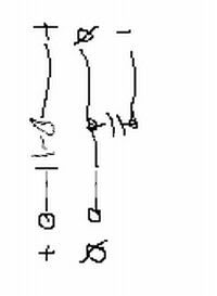
did I did it right ???
My AlephX don’t make sound...
I connect everything, apply voltage ...transfer from balanced to unbalance (place 4.7uF in series with +, and place another 4.7uF from – to 0) connect unbalanced + to + and 0 to 0...
No smoke come out of amp...only R4 and R1 gets really hot to touch...I play some 100Hz sound from WinISD via PC and preamp...
Voltage on amplifier was 16-0-15.4V...
I have use ztx450 instead of mpsa18 but I don't think that there is a problem...maybe I did not connect right input...
This is the way I done it
did I did it right ???
Yoke
Before applying any signal you will want to make sure that the DC values are OK all over the amp. R1/R4 getting hot means that too much absolute DC is present at the outputs. (That is from output to ground and should preferably be less than 1V).
What about R44/R45 ?
Assuming your amp is technically OK, you should be able to adjust that DC with VR2.
/Hugo
IThink I did some mistake...
I have 11V from output to ground, from one and other side : 
what to do, what to check...
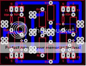
whell I could start from the beginning...I have made two pair per side ( 8 mosfets total for one chanel )...I have design my own PCB for that...maybe I did some thing wrong there
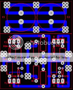
whell I will have to see how I connect it and post it here...
I don’t have digital camera so I can’t post pictures of what I did...
I hope that you can read ( R7A, R7B, R5A,R5B ...)
I have 11V from output to ground, from one and other side
: what to do, what to check...
whell I could start from the beginning...I have made two pair per side ( 8 mosfets total for one chanel )...I have design my own PCB for that...maybe I did some thing wrong there
whell I will have to see how I connect it and post it here...
I don’t have digital camera so I can’t post pictures of what I did...
I hope that you can read ( R7A, R7B, R5A,R5B ...)
I have magnifying glasses but I'm not that good in readingyoke said:
I hope that you can read
First thing of course is good connections, solderings.
Second thing, make sure your current source and diff pair works.
Check the voltage across R23/R25. Something between 4V and 5V is OK
/Hugo
voltage across R23 and R25 is 0.51 and 0.55... ( this is vith 16-0-15.4 V )...but any way it's too low...
what do you think could it be bad solder somewhere...
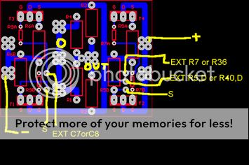
I have use D1a , J1a, Q6a , jumper R48, jumper R21...My R5,R6,R40,R41 are 0.5Ohm...the rest is the sime as AXR1.0...
what do you think could it be bad solder somewhere...
I have use D1a , J1a, Q6a , jumper R48, jumper R21...My R5,R6,R40,R41 are 0.5Ohm...the rest is the sime as AXR1.0...
Yoke>
what is your voltage over R5,6,40,41?
Which option 1 you choosed?
Are R46,47 in place? Those are essential for canceling common mode offset. If you got very high common voltage near positive rail (?) and the voltage over R23 and 25 is 0.55 V . . . let me ask you a perhaps stupid question: Is the bottom end of R17 connected to ground or hangign not connected anywhere ?
Piotr
Hello to all DiYer comunity!
Better late than never, I just finished my Aleph-X monoblocks. I've been thinking about such a topology since 10 years, but only Mr. Pass did the real think! Thanks to your good will, being a source of enlightment to other human beeings and taking the advatage of knowledge from all good people on this board, I managed to do this masterpiece of elektronics, now in my home. Thank you Mr.Pass and all of you R&D!
Back to electronics: after a few houres of analising the circuit, I figured that after making some alterations it schould run on single supply. I disconnected the PS middle zero from the amp's ground, disconnected R1,4,44,45 from ground , leaving them together acting as an 62 Ohm resistor hanging paralelly to the speaker, mooved the bottom end of R17 to negative rail (R17=4,7kOhm). With the R19 & R29 ends, that were previously grounded I made a node of virtual zero, linking this node to positive and negative rails with 220 Ohm/2W resistors paralleled with WIMA 220nF MKP10 caps. The input GND connect to this node too. After a while of hesitation I swiched this on and. . . it worked without smoke at all
Now I was curious how this modification influences the common and diferential DC offsets. Having crocodile clips wires I connected back the grounds returning to oryginal design while monitoring ofsets. No changes at all!
Then arrived time for listening test for this mod. The audience could hardly find any diference, pointing that with floating ground the base is a little more open, free or bigger than comparing to original circuit on which the base sounds more tight.
Now I'm supplying my AlephX with single 42V surce, biasing @6.5A in total. The CRC network is: 55mF, 0.4Ohm, 55mF giving ripples of 50mVpp which is allmost inaudiable when closing ears to the speaker.
Having potentially 112WRms on 5.5 Ohm I'm absolutly happy with the sound which is open big and amasing. Previously I've been using some others good amplifiers but the result of AlephX overlaped my expectations. The detaility is so good! Now I hear the facture nuances of every sound and the timing let me precisely hear each note!
Ounce again many thanks to all of you involved in developing of this project!
Piotr
P.S. And finally in winter time I don't have to use spare heaters

With R17 hanging, you have no current in D1, and the CCS (Q6) won't turn on. This would lead to the low voltages you see on R23/25 since no current it flowing in the differntial pair. You can either ground it or connect it to the negative rail as Piotr did.
If you go to the negative rail, watch the dissipation in R17 and current flowing through D1 - R17 will need to be increased in value and possible be a 1/2 watt or 1 watt resistor, depending on your rails. Piotr's 4.7K R17 sets about 7.5 mA through D1, and dissipates about .23 W. I'd use a 1/2 watt resistor there.
If you go to the negative rail, watch the dissipation in R17 and current flowing through D1 - R17 will need to be increased in value and possible be a 1/2 watt or 1 watt resistor, depending on your rails. Piotr's 4.7K R17 sets about 7.5 mA through D1, and dissipates about .23 W. I'd use a 1/2 watt resistor there.
Yoke>
The anode of D1a connect to R20&R17, than R17 have to be grounded or pulled to negative rail directly in case you omited Q12a & Q12b. This make the CCS to open a constant curent flowing down throu Q5 and Q7 which make voltage drops over R23,R25, which setup the Q2 and Q11 gates, opening the curent flow on main output devices. If the rest of your wiring is OK the circuit schould work ! Take Bob's look at power on R17.
Hope you will hear the music now Piotr.
The anode of D1a connect to R20&R17, than R17 have to be grounded or pulled to negative rail directly in case you omited Q12a & Q12b. This make the CCS to open a constant curent flowing down throu Q5 and Q7 which make voltage drops over R23,R25, which setup the Q2 and Q11 gates, opening the curent flow on main output devices. If the rest of your wiring is OK the circuit schould work ! Take Bob's look at power on R17.
Hope you will hear the music now
Piotr.- Home
- Amplifiers
- Pass Labs
- Aleph-X builder's thread.