Absolute DC Offset
It took me about a 10 days to get the abs DC offset right.
It initially seemed that I couldn't get it to stabilize under 1.5 volts. At present, it operates as follows
Turn on about 3.5 Volts offset
1 hour 1 Volt offset
2 hours or more +/- 100mV offset
I think in my case it takes quite a while for the amp to reach thermal equilibrium because of its size. The heat sinks will reach temp in about 30 minutes but the rest of the amp takes awhile.
Scott
Protos: it will depend on the operating temperature of your amp and how long it takes to warm up. With mine, the DC offset starts at 2V cold and goes to zero within about 15 minutes. But my amp is fan-cooled and warms up pretty quickly. I didn't like that power-on offset so I am playing with a DC servo design. The serv o eliminates the adjustment altogether.
For Rob Dingen
I'm posting this response here for Rob Dingen, because his email doesn't work correctly. His question was about how to very accurately match FETs for both Vgs and tempco. I said:
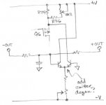
First I made a high-precision current source, which provides the same
current regardless of temperature. I hope you'll excuse the extremely
bad drawing:
Secondly I attached the FETs to be tested to a very large heatsink, to
test their Vgs when cold, and then I attached them to a heater at 30C to
test them when hot.
I'm posting this response here for Rob Dingen, because his email doesn't work correctly. His question was about how to very accurately match FETs for both Vgs and tempco. I said:
First I made a high-precision current source, which provides the same
current regardless of temperature. I hope you'll excuse the extremely
bad drawing:
An externally hosted image should be here but it was not working when we last tested it.
Secondly I attached the FETs to be tested to a very large heatsink, to
test their Vgs when cold, and then I attached them to a heater at 30C to
test them when hot.
Hi jwb
Thanks for the schematics.
You also match the IRFP240 that way?
And after which time do you measure?
I build a +/- 30v powersupply and a current source for 12.5 ma.
I used a half of a dip8 socket and place the 9610 in and wait 5 min and measure vgs.
After 4 min the vgs is getting stable and the voltage drop is getting very slow.
I had my old E-mail address so I changed it.
Rob
tester
jwb
I like the current source idea. When I matched mine I was the current source adjuster using my variable power supply. A little tedious.
I tested at two currents for the 244's. 200 and 600mA. Started at 200 for 30 seconds, measured, and then jumped to 600 mA for an additional 30 seconds and measured. I tried to keep the cooling between fet tests similar to get decent results. I think by doing it this way I rejected alot of parts out of my original supply that would have been happily matched.
To get an absolute temperature reference I have been thinking about using boiling water as a temperature source and then clipping the FET under test to a copper bar that sits in the water. This way the fet doesn't get wet and it quickly will reach a temp of 100C. (I know about the altitude effect) In this mannor the juntion temp is closer to real life operating conditions.
Any thoughts on that?
Banned
Joined 2002
Coulomb said:Here is thought you are all nuts!!
")
Anthony
Were all nuts but at least we use them : O ) TEE HEE HEEE
protos:
Wow, I haven't experienced anywhere near that much thermal variation. At most, I'm seeing +1.4V to 0V from cold to fully warmed up. Do you have the MacMillan resistors installed (R46/R47 on my schematic)? With my prototype channel, nulling the absolute DC did nothing for the differential offset (actually made it a hair worse, as I recall).
I have an idea for a simple two-transistor servo which could be connected to the existing Aleph-X circuit to null it's absolute DC offset (see attached image). Basically, this circuit just adds and subtracts current directly from the main CCS, thus affecting the absolute DC offset. A pair of equal resistors forms a voltage divider between the outputs, thus removing the differential-mode signal, and a cap forms a low-pass to help further attenuate stray signal voltages at the servo diff pair input. R1/4/44/45 must remain to keep the open-loop absolute DC gain low, though the MacMillan resistors would be rendered redundant and could be removed entirely. I provided a trimpot to control the overall current through the servo diff pair. This can be trimmed so that when operating at normal temperature, the servo diff pair sees roughly equal currents on each side, or as needed to prevent servo saturation when the amp is cold and coming up to temperature. With the servo installed, VR2 becomes useless for adjusting DC offset, but can instead can be used for additional control over current balance in the servo circuit.
BJTs should be low noise types, and I haven't done any calculations, since it's still just an idea I scribbled down on a post-it. In practice, some emitter degeneration resistors may be needed for the servo diff pair. In fact, the servo should have a low-noise CCS of it's own for best results, but you get the idea here.
Attachments
SGregory:
In theory, if you used deionized water, you could completely submerge the DUT, since pure water is supposed to be non-conductive. I've never tried it myself, but with a constant-current source feeding the DUT like in jwb's pic, the worst that could happen is the water would short out the device, and you'd get a voltage reading of 0V Vgs... no harm done. For the diff pair, I would not heat the water to boiling temp, though I understand your motivation to do so, since it provides reliable temp regulation of the water, and gets the silicon close to it's actual oprating temp. In practise, the diff pair will be quite a bit cooler. Perhaps an aquarium heater would be the way to go?
I would make one small addition to jwb's circuit: a momentary-off switch to short out the LEDs. This way, the current source only turns on when you press the button, allowing you to do very quick momentary tests while the silicon remains normalized to the water bath temp. Rail-to-rail opamp would be needed, or maybe a discrete circuit.
Hi Chad,
I guess an op-amp, as jwb suggested, would also work here.Would the ZTX450 work here as well?It should be ok no?
I just don't get how a small variation in current at r24 could cause such a huge shift of DC offset.After all we are talking about a "constant" current source?
Can somebody explain please?
What about the thermal drift ?I guess the current source and diff pair pass more or less current at different temps but I am seeing several volts for very few degrees.As I said before , the moment I lift the lid of the amp to adjust anything the DC offset may change up to 3v in about 20 secs without touching anything else so I can't even adjust it properly.
Of course my front end is running at up to double the bias which might explain a wider variation than some others ......but still it's too much of a change for me to be really comfortable with.
It's a bit like trying to balance on a surfboard with one foot in the air.( I have been trying to find a picturesqe analogy).
High Sensitivity to thermal changes
Protos,
I know you asked this of Chad. But I had an extra 2cents in my pocket so I thought I would give them to you. Being THAT sensitive to thermal changes as quickly as you describe is pointing to some other problem.
1) Looking back at my notes when I started my amps up, I did find that the amp was more sensitive to the diff pair when I had the main ccs bias (vr1, and vr3) turned way down. However, not anything like you are describing.
2) Have you measured the ccs for the diff pair. Is it being effected by thermal changes?
3) Are you using c11? What options are you using for the voltage reference on the Diff pair ccs?
4) What does the relative DC offset (between + and - ) do when you pull the lid off?
This problem could be as simple as a cold solder joint causing a thermal junction.
The rate that your amp responds to temperature changes makes it a pretty good thermocouple transmitter. I find that when I take the lid off of my amp the absolute DC offset will change .5V max over 20-30 minutes which gives me plenty of time to adjust the diff pair current.
I hope this helps.
Scott
MOSFET equivalent
I asked this question in another thread but did not get any response yet, so maybe better luck here:
Will any of the following be good substitutes for IRFP044 (in Aleph-X application):
Basic comparisan:
.................: Vdss Id Pmax Cin Cout
IRFP044......: 60 57 180 2500 1200pF
MTP52N06V.: 60 52 188 2660 810
NTP45N06L..: 60 45 125 1700 480
http://www.onsemi.com/site/products...P52N06V,00.html
http://www.onsemi.com/site/products...P45N06L,00.html
I noticed they are in TO-220 packages, but I always mount these with a flat "spreader bar" across all FET's. Get very good mounting pressure and thermal conduction this way.
Hi Scott,
The diff dc offset doesn't change almost at all during swings of absolute dc offset.I am not using c11.I am using a normal 9v zener with 1.5k to neg rail - I am thinking maybe this might influence things a little bit but probably not.I will measure the ccs soon hoever the voltages over r25/23 are pretty steady so I don't see how the ccs could be swinging around too much.
The diff dc offset doesn't change almost at all during swings of absolute dc offset.I am not using c11.I am using a normal 9v zener with 1.5k to neg rail - I am thinking maybe this might influence things a little bit but probably not.I will measure the ccs soon hoever the voltages over r25/23 are pretty steady so I don't see how the ccs could be swinging around too much.
potos,
Change r17 to to 3 to 5k. I would think that your D1a is getting quite warm. What is your rail voltage? In the original design r17 was to limit the current to around 5 or 6 mA across the zener. So use V=I*R. R=0.005/V(rail to rail) to obtain the correct value. I think what maybe happening is that the zener, at the power level you are operating it, may be influenced by cooling.
Scott
JDeV,
There has been lots of discussion on other fets. Any n channel FET will work in theory, the real decision here is how close to the edge do you want to live. TO220 cases don't dissipate as well as TO247 or TO3P. In my X I used the IRFP244 and run them about 33watts each with the sinks around 60C. I would keep the soldering iron handy if they were in TO220 cases. Were you operate the amp (chips) is up to you and your design.
Perhaps somebody can link to Nelson P's comment as to Fet transconductance vs. sonic signature. I couldn't find it and don't have the hard copy handy.
Scott
Hi Protos,
Yes, an opamp would also work, though my preference would be to stick with a discrete solution, as it gives more control over the open-loop parameters, and is just simpler overall. Just about any BJT with sufficient voltage rating and power dissipation will work there, ZTX450 included. There are other ways to do the discrete servo too. One could concievably remove R17 and replace D1 with a resistor, then reroute the servo diff pair to feed current to it, thus affecting the other side of Q6.
I calculate your zener is running at 14mA, if your rails are +/-15V... that's about 1/8W dissipation which is a tad high, but shouldn't present major problems. It would be worth bringing this down a bit as Scott suggested... a 4K resistor would be about right.
I wonder, are you using Q6a or Q6b? If you're using Q6b, it should be fitted with a small heatsink, as the little TO-92 gets much warmer than a big TO-220 will. Thermal variations in the CCS will mostly come from Vgs drift in Q6, so the greater it's temp variation, the greater the variance. Measure the voltage across R24 when the amp is cold, and again when the amp is hot, then you'll be able to see exactly how much the current is changing with temperature.
Hi
When I match the 9610 and wave my hand one time above it you inmediatly see the changes in VGS.
So if you put them thoghether it will be a bit better but the current source is standing alone.
If you look at the pictures from the XA200 you see that nelson is using heatsyncs for the diff pair and current source.
I think if you use heatsinks for the diff pair and current source the problems wil be smaller and much more stable.
Rob
For those interested in very large Heatsinks try this thread and Wikki.
http://www.diyaudio.com/forums/showthread.php?s=&threadid=30970
Regards
Anthony
http://www.diyaudio.com/forums/showthread.php?s=&threadid=30970
Regards
Anthony
- Home
- Amplifiers
- Pass Labs
- Aleph-X builder's thread.