Pass DIY Addict
Joined 2000
Paid Member
Hi Eric,
good thing you finally made it. Looking at the sine wave there must be a bug somewhere. How did you measure the bandwidth. This normally is narrower at 4R compared to 8R. In your case it's the other way round.
I raised the value of the McMillans for sonic reasons from 10k to 22k and beyond. The higher you go the longer it takes DC to come down. At the moment (with the PTC's) it starts at 1V and ends around 0V. I finished one DC-Servo and maybe I´ll manage to put it in the amp this week.
cheers,
William
Last edited:
Pass DIY Addict
Joined 2000
Paid Member
I replaced the 9v Zener with a 12v Zener and things appeared much better (same orientation as before). Sine waves now symmetric, square waves looked respectable (certainly better than it was with 9v Zener but not quite back to what it was with the 9610 input -changing the feedback cap might make further improvements though).
And then I wiggled one of the wires... Offset went nuts. one side went to almost 20v, I had 9vdc across the speaker terminals, and lots of fuzz on the scope. Grrrrrr... So, I removed the whole daughter board. Back to square one, but having tasted the input with JFETs, I want to make this work!
I'm trying to design a new approach. I'm thinking of attaching posts/socket to the main pcb so I can build the daughter board and just socket the whole thing down on the main PCB to avoid the wire runs all together. I'm half temped to put the 9610's back just to make sure I didn't damage the rest of the circuit.
Pass DIY Addict
Joined 2000
Paid Member
Well, I tried a clean and simple point to point circuit in an effort to eliminate the long wire runs that I think we're causing my hum. At the same time (which I think was a mistake) , I also reversed the diode connected to the 550's. My longest wire run was now less than 2cm.
Powered it up and I had full rail voltage on my speaker terminals.
I pulled the diode and put it back in as shown on the schematic, same result - full rail voltage across speaker terminals. So, out came everything again. The good news is that I haven't damaged any of my matched 2SJ74's - individually, they all still measure as before. So, either I toasted the 550's or something else on the main PCB.
Aiming for the more simple approach, how do I measure a ztx550 to see if it is still good?
This is becoming frustrating
Pass DIY Addict
Joined 2000
Paid Member
Looking at the sine wave there must be a bug somewhere. How did you measure the bandwidth. This normally is narrower at 4R compared to 8R. In your case it's the other way round.
This confused me as well. To measure bandwidth, I used a 5kHz sine wave and adjusted input amplitude until I got 10vRMS on the output. Then, I just increased the input frequency until output power fell to 70% of the original signal. I was really surprised when bandwidth was greater for 4 ohms than for 8 ohms...
I think in my first try with a daughter board for the SJ74's I had a bad wire. I used some CAT5 wire for my power supply wiring and as I was taking the board out, one of these wires broke. I must have cut it while trying to strip it for assembly.
Pass DIY Addict
Joined 2000
Paid Member
Thanks, William. I'm trying to see just what parts (if any) failed when things didn't go so well. If the 550's measure good (this would be a bad thing- I'll check tonight when I get home), what is the next most logical place to look for trouble?
I have a feeling the output mosfets are pretty robust, so they should be safe. Are Q6 that provides power to the differential, or Q4/Q9 (MPSA18) especially vulnerable ?
I have a feeling the output mosfets are pretty robust, so they should be safe. Are Q6 that provides power to the differential, or Q4/Q9 (MPSA18) especially vulnerable ?
Hi Eric,
nothing is that vulnerable. It depends a bit on what went wrong......
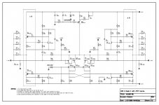
I would put the diode back in the right way and measure if the input bias is OK and what the drain voltages are over the two drain resistors.
Measure the bias of the output fets.
There aren´t that many active parts in an Aleph-X, you´ll find it
William
nothing is that vulnerable. It depends a bit on what went wrong......
I would put the diode back in the right way and measure if the input bias is OK and what the drain voltages are over the two drain resistors.
Measure the bias of the output fets.
There aren´t that many active parts in an Aleph-X, you´ll find it
William
Pass DIY Addict
Joined 2000
Paid Member
Pass DIY Addict
Joined 2000
Paid Member
OK - here is where things are. I checked each of my 550's and the SJ74's in the input differential - all measure good. I put the differential back on the PCB - I think I mixed up the wires on the Q7 side of the differential last time around.
I powered it up and here are the voltages I was able to read:
Voltage across source resistors for output mosfets Q1, Q10, Q2, and Q11 each start at about 0.6v and decreases quickly and begins to stabilize around 0.20v
Voltage across drain resistors for the input differential R23 and R25 measures 4.6v - same as it always has.
Offset across speaker terminal starts at about 2.0v and increases rapidly.
Absolute offset starts at about 3v on +speaker terminal and about +6v on -speaker terminal and increases rapidly.
Voltage across R44/R45 starts at about 7v and quickly rises to rail voltage. Same for R1/R4 on the other side.
Voltage across R2/R3 = 0v, same for R42/R43.
Any ideas on where to go next?
Pass DIY Addict
Joined 2000
Paid Member
Thinking about this more leads me to believe that Q6 has been damaged and this is what is accounting for the quick change in offset after power up. But since this is connect to the differential, why is my increasing offset not symmetric across the speaker terminals. Wouldn't a damaged Q6 affect both sides of the amp in the same manner?
I think I'll start tonight with replacing Q6, Q4 and Q9 to see happens...
I think I'll start tonight with replacing Q6, Q4 and Q9 to see happens...
Hi Eric,
if the current source doesn´t work anymore absolute dc offset will vary. The relative offset is not affected.
Since you measure around 4.5V over the drain resistors the current source probably works.
Having a wandering rel. offset points to the input diff pair (pairs)
William
if the current source doesn´t work anymore absolute dc offset will vary. The relative offset is not affected.
Since you measure around 4.5V over the drain resistors the current source probably works.
Having a wandering rel. offset points to the input diff pair (pairs)
William
Pass DIY Addict
Joined 2000
Paid Member
Pass DIY Addict
Joined 2000
Paid Member
Hi William,
You are correct about the JFETs not being broken. I pulled the differential again, fully disassembled it and measured the 550's and the SJ74's. Each measures correctly as a diode across the pins and the matched JFETs still match well. I also measured the empty holes on the PCB to make sure there are no hidden solder blobs on the back side of the board that are shorting across the pads.
Everything checks out. I also didn't find any loose solder joints among the input differential when I removed it from the board. I am happy to learn that I haven't blown up any of my parts, but this leaves me confused about what is causing this behavior.
With my first effort to replace the input differential, I did make a minor adjustment to the VR2 pot when I moved from the 9v to the 12v zener when things were working for a short period of time. Relative DC offset was in the 40-50mV range and Absolute DC offset started around 17v and declined quickly toward zero.
With my second effort to replace the input differential, I didn't make any adjustments to VR2 at all - I expected offset would just behave like the last time around and not need major adjustment.
So, here's a dumb question now that I have everything disassembled for a second time: Could this behavior just a result of needing to re-adjust VR2? It doesn't make sense to me that it would be this far out of whack from the last time around.
Eric
Pass DIY Addict
Joined 2000
Paid Member
Hmmm... Interesting insight, Zen. I didn't realize the input differential would be quite so sensitive. I was expecting it to behave as before, thus I didn't even think to adjust the current. I did use a second set of JFETs the second time around. It seemed so far out of whack, though, I was assuming something much more drastic was wrong. This is making me think I took it apart when all I needed to do was adjust the pot...
I guess I'll put it all back together again tomorrow night. I'm getting lots of practice designing a nice compact point to point circuit... More results in 24 hours...
I guess I'll put it all back together again tomorrow night. I'm getting lots of practice designing a nice compact point to point circuit... More results in 24 hours...
Hi Eric,
VR2 is for the bias current and sets absolute offset not relative offset.
If the relative offset is off the current through the diff pair is not distributed evenly.
This happens when they are not matched right or the source resistors are off or something else is not right. I saw your fets are thermally coupled. This means that normally temperature has no influence.
I can cook or cool my input fets without any influence on absolute or relative offset.
William
- Home
- Amplifiers
- Pass Labs
- Aleph-X builder's thread.