???plenty of original First Watt pictures....
Yes I have already seen photos, but I just ask has what his taken out hp serves known
I'm having a real hard time understanding the question after re-reading it 5 times.
Hello, I just finished my Nelson Amp M2 and I wanted to know what its used to twist the cables output hp between the cards and the terminals inside the amp? For I did not do it I cabler with wire hard of 1,5m. On a power supply I understand for the parasites that have the twists but on the output wires hp ....... Thank you for your help
Yes twist speaker outputs wires
")
Papa First Watt work show on the photo
Attachments
Thank you for your reply, sorry for the wrong translation I use google .... Yes I know it twisted but I just wanted to know the interest of doing it? If we do not do that it changes a few things?
If you are curious what happen just try not twisted them in your M2.
Some cross talk noise interferances ? Me think frenchglish
Attachments
Ok if work perfectly so don't need any changes.....The amp works perfectly....
Maybe 0.47R 5 Watts output source resistors upgrade to Mills or MPC74 but is not urgency.
Congratulations Uchu007 great quality diy work !
Enjoy

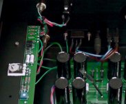
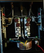
I re-purposed my F5 using M2 boards from Tea-Bag. They are in a 5U chassis which is a bit overkill, but the upside is no hum due to the auto-former being quite a distance from the mains transformer.
Getting the offset to null was fun...not. My offset was negative so I ended up pulling the boards and soldering sockets in place of R7. Then searching through resistors I had on hand ending up with 47.5k and 220R in series measuring 47.72k. This gave me enough adjustment with P1=5k, and R6 remaining at 47k. Then I just soldered the resistors into the sockets. It sounds simple, but it was a lot of trial and error.
Here are the pics to prove it really happened:
Thanks, the output resistances are mundorf MR5 0.47 ohms .... I increase the capacitors has 312000 uf and I confess that I am surprised by the quality of this amp, I think it takes a preamp now because My dac and may be a weak one ....
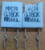
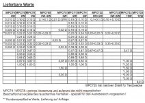
MPC74 are non inductive , non magnetic :
Resistance a couche metallique Fukushima Futaba MPC74 5 W 0,47 ohm 5% 0.47 Ω sortie radiale MPC74 5 W 5 % 1 pc(s) sur le site Internet Conrad | 443893
It's superb to try if compare with high price Hi-Fi boutique resistors , metal oxide and ordinary metal films.
I do myself experiments and is my keeper source 0.47R.
Have fun
I re-purposed my F5 using M2 boards from Tea-Bag. They are in a 5U chassis which is a bit overkill, but the upside is no hum due to the auto-former being quite a distance from the mains transformer.
Getting the offset to null was fun...not. My offset was negative so I ended up pulling the boards and soldering sockets in place of R7. Then searching through resistors I had on hand ending up with 47.5k and 220R in series measuring 47.72k. This gave me enough adjustment with P1=5k, and R6 remaining at 47k. Then I just soldered the resistors into the sockets. It sounds simple, but it was a lot of trial and error.
Here are the pics to prove it really happened:
View attachment 630900 View attachment 630901 View attachment 630902
Well done BRAVO Kevin !
My solution was 10K multiturns trimmer on the place of 5K
My solution was 10K multiturns trimmer on the place of 5K
Yeah I know, that would have been easier as it turns out. I didn't have a 10k trimmer so I committed to changing R7. Took me a little while, but it's all good.
I see you guys talking about the source resisters. I just used the standard Panasonic ones I had lying around. Do you recommend changing these out?
As a side note, I'm getting a loud pop when shutting the turntable motor off. It's always made a pop but now it's very loud...in fact it scares me a bit. The only thing I remember changing is the amplifier. I could switch back to the F4 to see if it makes a difference but it's out on loan to my brother. Does this make any sense? Any thoughts?
Last edited:
I have some Futabas laying around somewhere
Relax not urgencyI see you guys talking about the source resisters.
I just used the standard Panasonic ones I had lying around.
Do you recommend changing these out?
Can be funny to compare sound if you solder two of them but only on the one mono side of yours M2 channels.
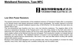
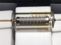
Strong parameter of Futaba source resistors are internal construction structure and materials.
Ordinary metal resistors or metal oxide are spiral looped...and is total of 5 elements not 3.
Only MPC74 (5 watts) and MPC78 ( 2 watts) are non magnetic versions.
" Bulk z-foils " on the budget hahaha.
BTW new Mr. Pass amplifiers are source resistors free !
Example : DEF
Attachments
Last edited:
You can see inside spiral and film grains in glass vacuum loaded resistor.
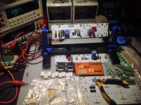
Instaled sockets for Toshiba and LSK jfet's roll & bench M2 experiments.
Stopped drinks beer's so get few more bucks i spend with pleasure on fancy components
Instaled sockets for Toshiba and LSK jfet's roll & bench M2 experiments.
Stopped drinks beer's so get few more bucks i spend with pleasure on fancy components
Attachments
As a side note, I'm getting a loud pop when shutting the turntable motor off. Any thoughts?
Your loud pop is if you shutting all tuntable power off
or is if your turntable stops for pause or vinyl change ?
Greetings
- Home
- Amplifiers
- Pass Labs
- Official M2 schematic