A big thank you to Wayne and Nelson for their selfless giving to the DIY community, great designs and all for the pleasure of making people curious to build and then happy they did!
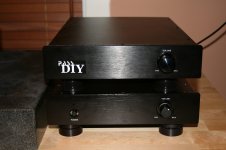
Pics are my Pearl 2 with B1 in same chassis (I don't have a preamp so this gets the job done without one). I can use the B1 with an Aux input (CD, DAC or what have you) or with the Pearl 2 using the switch on the right side panel. The rotary multipole and two pole switch in the middle of the chassis are for cartridge loading options (later).
Frankly it sounds really nice and I am super happy, the Pearl 2 is very natural sounding and the B1 by itself adds a nice touch of Neslon to CD and DAC inputs.
HELP!
The one area I am not sure if I got it as good as it could be is the noise from the Pearl 2. I built it originally with R14 at 362 for high gain and have since changed to 1K for stock gain. There is noise at both gain setups (for sure, more with the higher gain setup but not by that much). In listening with a high output MM cartridge the noise is of no matter but with a LOMC cartrdige I think it will be a big issue.
There is essentially no hum (there was but star grounding took care of that). There is a hiss and a high freq buzz (the buzz is a little louder than the hiss).
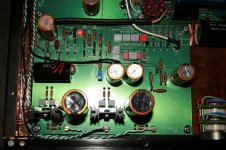
I also have a couple of voltages off from Wayne's drawing. I made notes on the attached:
1) Top of R25 is -22.5 volts (in both high and low gain configurations) vs the -26.2vdc in Wayne's dwg.
2) Bottom of R9 (collector of Q3 is) 12.5vdc vs the 10.1vdc on Wayne's dwg.
These measurements are the same ish in both channels. All other readings are good compared to Wayne's dwg and P1 is set to 0 with about 30mv of swing.
I have tried pulling one leg of R7 and putting a cap on R10 as I have seen mentioned in one of the Pearl 2 threads with no change. I apologize if I have missed any other suggestions already made
BTW, power supplies are Salas Back In Black shunt regulators, yes probably overkill but that is my way
If anyone has any advice I would be most appreciative!
Thank you all.
Pics are my Pearl 2 with B1 in same chassis (I don't have a preamp so this gets the job done without one). I can use the B1 with an Aux input (CD, DAC or what have you) or with the Pearl 2 using the switch on the right side panel. The rotary multipole and two pole switch in the middle of the chassis are for cartridge loading options (later).
Frankly it sounds really nice and I am super happy, the Pearl 2 is very natural sounding and the B1 by itself adds a nice touch of Neslon to CD and DAC inputs.
HELP!
The one area I am not sure if I got it as good as it could be is the noise from the Pearl 2. I built it originally with R14 at 362 for high gain and have since changed to 1K for stock gain. There is noise at both gain setups (for sure, more with the higher gain setup but not by that much). In listening with a high output MM cartridge the noise is of no matter but with a LOMC cartrdige I think it will be a big issue.
There is essentially no hum (there was but star grounding took care of that). There is a hiss and a high freq buzz (the buzz is a little louder than the hiss).
I also have a couple of voltages off from Wayne's drawing. I made notes on the attached:
1) Top of R25 is -22.5 volts (in both high and low gain configurations) vs the -26.2vdc in Wayne's dwg.
2) Bottom of R9 (collector of Q3 is) 12.5vdc vs the 10.1vdc on Wayne's dwg.
These measurements are the same ish in both channels. All other readings are good compared to Wayne's dwg and P1 is set to 0 with about 30mv of swing.
I have tried pulling one leg of R7 and putting a cap on R10 as I have seen mentioned in one of the Pearl 2 threads with no change. I apologize if I have missed any other suggestions already made
BTW, power supplies are Salas Back In Black shunt regulators, yes probably overkill but that is my way
If anyone has any advice I would be most appreciative!
Thank you all.
Attachments
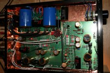
Are there any sources of interference inside the chassis?
Why all the copper looking sheet? Is this a plastic chassis?
Are all the copper looking sheet intended to be a screen?
How long are the caps at the seams?
A long gap lets in much interference.
How well are all the input cables suppressed for interference?
I see many twisted cable pairs, but I also see some single wires. LOOP AREA?
- Status
- This old topic is closed. If you want to reopen this topic, contact a moderator using the "Report Post" button.