if you're thinking of fiddling with (red marked) 10K resistor - there is no need for any kind ofpot ; just decrease it to first lower value if you're doubting that upper gate is demanding slightly more juice for non- oscillating work
also - if you look at :
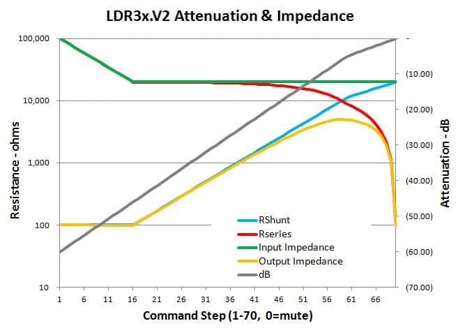
output impedance of your LDR attenuator thingie is nowhere near goo denough for feeding Papa's brick amp ; put regular 2SK170BL/2SJ74BL buffer in between
also - if you look at :
output impedance of your LDR attenuator thingie is nowhere near goo denough for feeding Papa's brick amp ; put regular 2SK170BL/2SJ74BL buffer in between
if you're thinking of fiddling with (red marked) 10K resistor - there is no need for any kind ofpot ; just decrease it to first lower value if you're doubting that upper gate is demanding slightly more juice for non- oscillating work
also - if you look at :
output impedance of your LDR attenuator thingie is nowhere near goo denough for feeding Papa's brick amp ; put regular 2SK170BL/2SJ74BL buffer in between
OK!
I do have some K240BL's left so I will find a buffer circuit. Any ideas?This has been what I thought all along.
On the supplies, I have the variac, iso transformer and caps all ready. I asked the question to Papa in the thread about which way to go - bench supply or cap bank and his reply was a "DC-coupled, low impedance" drive is needed for the circuit. He also suggested to start with the bench supplies first.
Well, my cap bank would have been 4x 68,000µF/80V for each channel so not having to build it and risk certain death with one wrong move is a good thing. But I am ready to take it on if that's what's called for.
ZM,
What - you don't like my AB 10K pot
The only reason to lower 10k resistor is if you have less than the desired current through the constant current source. This is the least of your problems at the moment.
Focus on proper power supply first. Once the amp is operating correctly you can consider lowering 10k resistor if you need more current.
OK!
I do have some K240BL's left so I will find a buffer circuit. Any ideas?This has been what I thought all along.
Use the buffer in Sony Vfet article Part 1
Use the buffer in Sony Vfet article Part 1
I still don't know why the bench supplies are not working with the circuit the way it is set up. Until I do, how would I know what to avoid? In an earlier post, I asked Papa if the CSX1 PSU would work well with this, and to the best of my ability to decipher, his suggestion may be something else. I will look into it.
If it does looks like I have to build the cap bank after all, that should keep me busy for a bit. When that's done, I will start tackling the buffer.
try with plain PSU - variac , xformer , cap bank
I had problems with lab supply feeding steady high Iq in past ...... and I don't care what was in question
using variac + big Donut + big cap bank is saving me of too much thinking
ZM,
The R&S lab supplies are pretty tough and are rated at 32V 5A continuous, 10A for an hour and 20A for 1mS. In my stress test using a 8 Ohm Frizlen braking resistor, they did not break a sweat and were rock steady - they drew exactly 7.1A at +60V.
What's puzzling is the current throttling that I am seeing on the supplies' meters, especially after the devices warmed up. Something in the circuit must be causing this to happen. And I would like to know why to avoid it.
By the way, I had already laid out an AC/DC PSU with the Variac before deciding to build this amp. It would be a 1kVA box with an iso transformer so I can use it to play music or safely fix amps. Attached is a print from the FPD file of the front panel. The 2 smaller circles are for power and AC/DC switches and the 4 larger circles are for Simpson panel V and A meters. Just haven't built it as the amp project got my attention after BAF.
Attachments
May I repeat two suggestions...
1. In Aleph P1.7 the Zener in the input caused oscillation with me and some other people.
Take it out.
2. Lynn analyzed in the F6 circuit a tendency of motorboating by simulation and he adviced as far as I remember to reduce the 100uF cap near the Jensen to a smaller value, 220uF.
1. In Aleph P1.7 the Zener in the input caused oscillation with me and some other people.
Take it out.
2. Lynn analyzed in the F6 circuit a tendency of motorboating by simulation and he adviced as far as I remember to reduce the 100uF cap near the Jensen to a smaller value, 220uF.
May I repeat two suggestions...
1. In Aleph P1.7 the Zener in the input caused oscillation with me and some other people.
Take it out.
2. Lynn analyzed in the F6 circuit a tendency of motorboating by simulation and he adviced as far as I remember to reduce the 100uF cap near the Jensen to a smaller value, 220uF.
Hi Gerd,
Thanks - I will look into it!
well , in that case (bench supply proven) , you can exclude it's responsibility to oscillation
do you have a scope , by any chance ?
to exclude problems with bias generator , you can go with 9V battery and 2K2 trimmpot across it , as temporary test substitution
ZM,
Well, I think the bench supplies are good, but it is possible that there can still be unintended interactions. This is why I am trying to understand the root cause before attempting a fix. And I will try the 2 suggestions from Gerd to see if that makes any difference.
The least destructive/disruptive test is your first suggestion, changing the 10K in the bias loop. Tomorrow, I will hook up my pot and see if I get anywhere. If the bench supplies still motor-boat or oscillate then it's time to build the Variac PSU. Not looking forward to it because the front panel has to hold the weight of the Variac, which is about 25 lbs. Total weight, 80+ lbs.
I do have a scope - but it's in storage. I am waiting for the QA401 to be released so I can get a competent, poor-man's AP to use both for time domain and THD+N measurements.
Last edited:
sorry my ignorance - what's QA401 ?
That's Quant Asylum's soon-to-come audio analyzer: QA405 and QA401 Status - QuantAsylum
ZM,
Well, I think the bench supplies are good, but it is possible that there can still be unintended interactions. This is why I am trying to understand the root cause before attempting a fix. And I will try the 2 suggestions from Gerd to see if that makes any difference.
.
Assuming I understood ZM idea of 9V battery and trimpot for 4.7V source.
I think you should proceed with this first.
When I was doing Id vs Vgs curves for p channel mosfets using separate supplies (one for Vds and one for Vgs) I had big headaches. In the end I pulled out my Nelson Pass Mosfet tester to do it, problem solved.
So definitely try ZM's idea first.
2pD
OK, I'm open to trying.
But what I don't understand is how using a battery for the 4V7 bias supply is so different than my bench supply, which is linearly regulated and known to be stable and can be accurate to the µV level. In fact, most of the current and voltage gyrations were happening in the rail supplies, and the bias supply was rock steady. It was last calibrated in 2012 at the factory.
Yes mine is also linearly regulated too.
I'm not saying it's not possible to make it work with the lab supply, just that it can be prone to giving you headaches.
Also if you look at my eSCAPEd Goat thread you will see my lab supply gives higher overshoot on square waves compared with CRC supply.
Anyway the battery is a very quick thing you can do to either eliminate the lab power supply as a problem or not. Once you have established that you can decide how to best tackle the problem.
I just remember that I had motorboating at the F6 only, when I made in my point to point arrangement the fault to mix up two of the wires of the Jensen.
Another possibility.....my apologies Mr. Pass....one of the dots in the circuit is on the wrong place.
I am too dump to jugde this....but Zen Mod can.
Another possibility.....my apologies Mr. Pass....one of the dots in the circuit is on the wrong place.
I am too dump to jugde this....but Zen Mod can.
That's Quant Asylum's soon-to-come audio analyzer: QA405 and QA401 Status - QuantAsylum
Thanks! that's what I am looking for also...
After receiving the various suggestions on bringing the amp to life, I went back to "work" and try to make it work. But before I implemented the changes, I thought it would be smart to isolate the major issues. They are:
1. Power draw is not as expected. I started with +60V, limited to 4A. I measured +26V at the gate of the output device. However, once the output device warmed up, the voltage draw dropped from +60V to about +32V, and the current draw kept trying to push beyond the set limit of 4A. The temperature of the output device was about 160°F. So I increased the current limit to 4.5A, and the result was that it was all quickly "absorbed", with the voltage staying around +32V, current draw at 4.5A, and the temperature of the output device rising to 190°F or so. At this point, I stopped.
2. Motor-boating or oscillation was happening with the input shorted. Since I could not solve the current draw issues, I did not attempt the suggestions from Generg.
ZM suggested changing the bias regulator 10K to a slightly lower value such as 8K2 or 6K8. I did this by connecting a 10K pot as a VR. Changing the pot did not show any impact on the current draw. He also suggested to use a 9V battery with a 2K2 trimpot as bias supply and the idea was seconded by 2picoDumbs. I do not have a 2K2 trimpot so I have not tried it yet but cannot see how that could be the cause, having seen that the bias supply has been completely stable.
So that is the current state of affairs. My first priority is to find stability in the power supply and current draw as intended by the circuit. Then I will address the motor-boating issues.
I want to say thank you to all those who have shared their wisdom with me, even if we are not there yet.
- Status
- This old topic is closed. If you want to reopen this topic, contact a moderator using the "Report Post" button.
- Home
- Amplifiers
- Pass Labs
- BAF 2015 Coverage