So, I might be looking into building an F5. To learn some things and also see what the various components are doing, I wanted to simulate the amplifier.
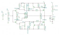
So I got myself Tina Spice from TI, and put the schematic in there. I found some models for the JFET's and the rest of the stuff was already present. All good so far")

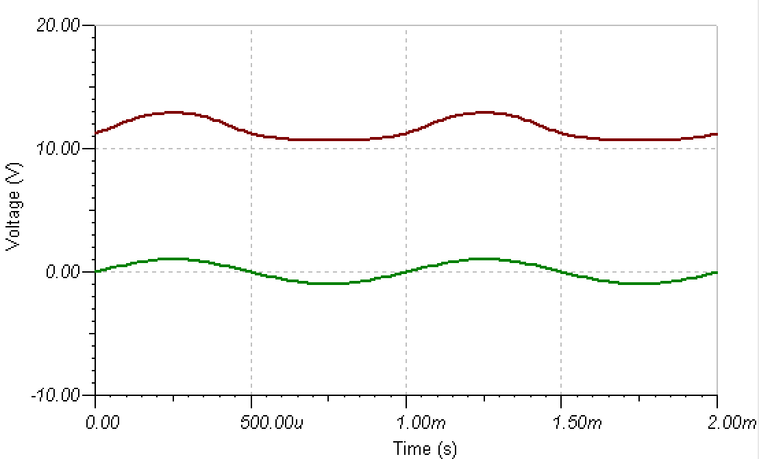
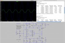
So I virtually powered up the amp and played a nice 1kHz note. The trouble is, the output has a gigantic DC offset of more than 10 volts. I tried various settings of P1 and P2, but that did not do much. Also the waveform is a fair bit distorted:
Now I know simulations have a fair bit of limitations. This is however a big difference with the real world. Therefore I must be doing something wrong. I did find an offset in other amps I tried to simulate (also MOSFET amps).
Furthermore, I'm wondering if anyone ever tied lateral MOSFETS from Semlab, for instance ALF16N20W/ALF16P20W? What would need to be changed to accomodate these? They also have a dual version ALF08NP16V5, which is only rated at 8A (per MOSFET), but might be used in a setup like the F5 Turbo V2 (so paralelling two of them)?
So I got myself Tina Spice from TI, and put the schematic in there. I found some models for the JFET's and the rest of the stuff was already present. All good so far
So I virtually powered up the amp and played a nice 1kHz note. The trouble is, the output has a gigantic DC offset of more than 10 volts. I tried various settings of P1 and P2, but that did not do much. Also the waveform is a fair bit distorted:
Now I know simulations have a fair bit of limitations. This is however a big difference with the real world. Therefore I must be doing something wrong. I did find an offset in other amps I tried to simulate (also MOSFET amps).
Furthermore, I'm wondering if anyone ever tied lateral MOSFETS from Semlab, for instance ALF16N20W/ALF16P20W? What would need to be changed to accomodate these? They also have a dual version ALF08NP16V5, which is only rated at 8A (per MOSFET), but might be used in a setup like the F5 Turbo V2 (so paralelling two of them)?
Attachments

use LTSpice
Well, that helps
Found a working model here.Now for my follow up questions.. Who knows? In the meanwhile, I'll play with the sim

Attachments
you can find LTSpice models for laterals ..... play and think
already done , some prefer verticals , some laterals
just search on forum

Yeah, just found some of the semlabs models (just not for the dual version). They seem to work in the simulation, but distortion is nowhere near as good as the IRF's. It appears to be mainly 2nd order though, while the IRF's have much more 3rd. I'll play with that a bit more I guess
I also found the problem with the Tina model: the upper IRF was connected wrongly.
Last edited:
Laterals have less transconductance so less feedback if used in F5.
A few years ago I built a folded cascode front end but ran laterals as source follower.
It looks very similar to the Nelson's new SIT push-pull (Sony Vfet Pt2) amp except biasing is much simpler with laterals on the output.
Something like that is a very nice amp.
A few years ago I built a folded cascode front end but ran laterals as source follower.
It looks very similar to the Nelson's new SIT push-pull (Sony Vfet Pt2) amp except biasing is much simpler with laterals on the output.
Something like that is a very nice amp.
Last edited:
Laterals have less transconductance so less feedback if used in F5.
A few years ago I built a folded cascode front end but ran laterals as source follower.
It looks very similar to the Nelson's new SIT push-pull (Sony Vfet Pt2) amp except biasing is much simpler with laterals on the output.
Something like that is a very nice amp.
Well, I think my analog electronics knowledge is a bit to far behind for that kind of stuff, and sadly, I currently don't have the free time to catch up. Far to much other stuff on my mind.
I did however tinker a bit around with simulations of the F5 and F5 Turbo (V2), and it is great fun. Conclusion is that it is just best to build the thing the way Pass designed it. It is about as good as it gets for people like me I guess
So suppose I'd like to build the F5. I'm using a 5 unit Open baffle (WBBMT) with active filtering. The woofer I'll do with a Class-D amp (have a few lying around). The two basses are paraled and are therefore 4 Ohms. The mid is 8 Ohms, and the tweeter is 4 Ohms (NEO3PDR). Therefore I need the F5 to be comfy at 4 Ohms. And I'd need six of them
Power wise, I don't need a whole lot. Currently I'm using a tiny T-amp for the bass to tweeter, and that is loud enough for me. An F5 will play much louder still.Now here is the thing: I'd like to put all six of them in a single case
. I thought of the biggest case of hifi2000, with 4x0.19 C°/W sinks. Pass says you need about 0.6 C°/W per transistor, or 0.3 C°/W per amp. If I do a quick calculation (correct me If I'm wrong here), the case would give me 0.285 0.3 C°/W per amp. So I guess I'm good here?Power supply... Well, I do have a 1kW SMPS. I only need to figure out how to lower the voltage quite a bit (working on that). It should be able to give me 16A of current per rail (19A peak). A quick calculation shows that this might be a tight fit? To tight? I could lower the bias to about 1A per device?
define needed power for each way-amplifier
Who knows what one will ever need
. I know that the current setup with the tiny T-amp delivers ample power. I'd like a bit more of headroom tough, and I'd like to keep the amps mostly the same in terms of Iq.My first inclination would be to build a F5 with slightly higher rails (about 30Volts), and with a Iq of about 1 Amp. That would mean about 120W of heat per amplifier, and 12A of total current draw from the PSU with six channels.
you'll not get mucho cojones with 1A Iq @ 4 Ohms
rethink ..... what power you need and in how much ways .........
take in account that lowest register is taking at least 60% of power
you can power them from same PSU/voltage , but with highest Iq for lowest F. , decreasing Iq going to upper F.
good plan is more than half work
you'll not get mucho cojones with 1A Iq @ 4 Ohms
Yeah, you might be right there...
rethink ..... what power you need and in how much ways .........
I think 50 Watt's per amp is more than enough, tweeter could do with 25 or 30 I guess.
good plan is more than half work
I agree! That's why understanding this stuff is important. So let me make some observations. Correct me if I'm wrong:
- For the same Iq, I get less class A power into a 4 Ohm speaker than a 8 Ohm speaker
- Likewise, because we can dump more current per voltage, I do get more AB power into 4 Ohms
- For the Turbo version, when having the same Iq as a normal, means I burn x times the power (both heat and juice), where x is the number of output devices
- Status
- This old topic is closed. If you want to reopen this topic, contact a moderator using the "Report Post" button.
- Home
- Amplifiers
- Pass Labs
- Help with simulation of the F5