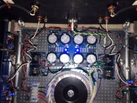
Yeah, now 2 channel connect 1 earth, old version had 2 separately earth ground.I recently re-wired the earth again in a different configuration
Although there was nothing actually wrong with the first version as by chance I heard a slight hum in my speakers
The second version uses more earth points, and has done the trick
The F6 is now silent
FR
Found/saw a Very nicely made heavy Ali Baking pan  6" x 3" at a local commercial Kitchen supply house. ~6$
Question is : IS ali a worthwhile material for enclosing shielding a PS torroid ?
I've read that mild steel, even tinplate is superior at containing 60hz Hummmm.
If true, then even a repurposed tinplate biscuit tin would be superior ?
6" x 3" at a local commercial Kitchen supply house. ~6$Question is : IS ali a worthwhile material for enclosing shielding a PS torroid ?
I've read that mild steel, even tinplate is superior at containing 60hz Hummmm.
If true, then even a repurposed tinplate biscuit tin would be superior ?
help needed
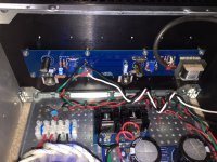
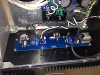
need help troubleshooting F6
PSU 25.4v
completed wiring to pcbs and am trying to set bias and offset, I'm not getting anything across the .47 resistor, clipped a lead on each side and all i get are 0.00
I get .022v on RT channel .027 across LT channel speaker outputs
went ahead an tested with a speaker to see if I have sound and I don't.
wiggled components, checked solder joints etc etc
help
Attachments
need help troubleshooting F6
PSU 25.4v
completed wiring to pcbs and am trying to set bias and offset, I'm not getting anything across the .47 resistor, clipped a lead on each side and all i get are 0.00
I get .022v on RT channel .027 across LT channel speaker outputs
went ahead an tested with a speaker to see if I have sound and I don't.
wiggled components, checked solder joints etc etc
help
You have to do a lot of turning on the bias pots. Maybe you just have not turned enough.
Found/saw a Very nicely made heavy Ali Baking pan
Question is : IS ali a worthwhile material for enclosing shielding a PS torroid ?
I've read that mild steel, even tinplate is superior at containing 60hz Hummmm.
If true, then even a repurposed tinplate biscuit tin would be superior ?
I have bought this item 15cm version and it's good value, it should fit decent toroid size.
Audio DIY Needed Metal Shield Plate Cover for Toroid Transformer with Many Size | eBay
Dummy test with speaker ferrit magnet sticked to internal side, measured on the other side with android phone and only got 120uT, where earth magnetism is measured 40uT. I think that toroid magnetic field should be blocked well
Last edited:
I think so, the band goes towards the point correct. ?Did you check, zener s polarity? Check 0.47r,0.56r,100r resistors and mosfets.
The problem appears to common to both boards. Check your ground scheme and be sure you are getting + and - and have the ground correct. The PS ground has to be correct or neither board will work. Unless you have incorrectly installed something or something has failed on the boards it will work. I think I remember having the same problem on one of my first builds and my common ground for the PS was not correct.
Then it has to be something wrong with both boards. You will probably have to pull the boards and check everything unless you have some knowledge of troubleshooting and the equipment to do it. Not that many parts to check on F6. Pull one board to start with. Maybe others will join in and give their opinion. Where did you get the jfets?
Everything came from the Diy store. And I will pull one and start.Then it has to be something wrong with both boards. You will probably have to pull the boards and check everything unless you have some knowledge of troubleshooting and the equipment to do it. Not that many parts to check on F6. Pull one board to start with. Maybe others will join in and give their opinion. Where did you get the jfets?
I think so, the band goes towards the point correct. ?
The Zener's band always goes toward the more positive voltage.
Check the orientation of those jfets. I would definitely check the active devices first. Check the input transformers. Someone on the M2 thread broke some of the tiny wires but I doubt that is the case with your because it is both channels. Double check the zener's and make sure they are the right value. I took a look at the schematic to refresh my memory and there is not much to go wrong on that board other than the transistors and zeners which bias the circuit. It the jfets are in correctly I would pull one of the zeners first. Double check you have the right jfet in the right spot. Check R7 and R8 for correct value and P1 and P2 next.
Last edited:
thank you for the input and i will do some discover and post my findings.Check the orientation of those jfets. I would definitely check the active devices first. Check the input transformers. Someone on the M2 thread broke some of the tiny wires but I doubt that is the case with your because it is both channels. Double check the zener's and make sure they are the right value. I took a look at the schematic to refresh my memory and there is not much to go wrong on that board other than the transistors and zeners which bias the circuit. It the jfets are in correctly I would pull one of the zeners first. Double check you have the right jfet in the right spot. Check R7 and R8 for correct value and P1 and P2 next.
thank you for the input and i will do some discover and post my findings.
Persevere, it always seems so simple when you find the problem but is frustrating after building and having a problem.
And also check if you got the 9V1 zenerdiode installed, not the 5V1.....
Mine still has 9.1, as boards were assembled before that change. While I do intend to change them out at some point, mine runs fine, bias rock steady.
Russellc
Mine still has 9.1, as boards were assembled before that change. While I do intend to change them out at some point, mine runs fine, bias rock steady.
Russellc
I have not changed mine from 9.1 either. The change recommendation to 5.1 was made after I made my amp. I also have intentions of changing the zener and appropriate resistor some day I have not done so yet. No problems with the amp so far.
- Home
- Amplifiers
- Pass Labs
- F6 Illustrated Build Guide