Meanie, the amp looks great! Thanks for sharing!
Thanks Mikerodrig27,
This chassis fits perfectly for those using Conrad Heatsinks (350x151), it is available in Aliexpress for a very low price.
KYYSLB DIY Home Audio Box Case 285*150*370mm WA109 Aluminum Amplifier Chassis Class A Amplifier Pure Post amplifier Case|Amplifier| - AliExpress
Thanks Mikerodrig27,
This chassis fits perfectly for those using Conrad Heatsinks (350x151), it is available in Aliexpress for a very low price.
KYYSLB DIY Home Audio Box Case 285*150*370mm WA109 Aluminum Amplifier Chassis Class A Amplifier Pure Post amplifier Case|Amplifier| - AliExpress
That chassis is a good deal. I noticed that Conrad Heatsinks is in Australia. Their pricing seems reasonable though.
Hello.
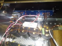
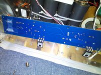
I have wired everything then tried with bulb tester.
PSU is no problem with 25V. The light off after few seconds.
But after connected PCB, The light was bright and didn't off.
I have checked Mosfet.Every middle pin (drain?)have shorted with
chaiss. I take out PCB from heat sink but one of mosfet middle pin
have still short with ground.
Can someone guess what happening?
Attachments
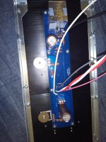
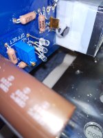
From your second photo, it seems that after you have tapped the exposed hole, there's a raised lip and maybe if that's common to the other tapped holes, this would be enough to punch through the insulation and short out the device -
I suggest you disassemble all the fets to check and maybe champher (remove that burr) with each tapped hole to make sure no edges remain - just saying, mind you - an easy oversight
I suggest you disassemble all the fets to check and maybe champher (remove that burr) with each tapped hole to make sure no edges remain - just saying, mind you - an easy oversight
I don't really have an answer for the health of the devices but suggest you just measure them in circuit to see if any are 'shorted' etc. You just might have escaped the 'smoke test' at the reduced 'bulb test' voltage level - fingers crossed.
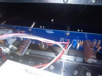
Do I see that 'triple led' upgrade there?
Another suggestion, if you're of mind, is to bypass the SuperThru caps on your power supply (neat job with the 'tie-wraps) with something like those green BP version about 470uF - or perhaps just attach some of those Silmics if you have some spare to see if it
I found that the "SuperThrough" [Nichicon KG(M)] were good next to the rectifier bridges and the "Elna for Audio" caps better after the resistor of the C-R-C supply - it seemed to improve the amps clarity and more 'punch' in the bass but maybe just in my setup too - those "SuperThrough caps are a bit of a puzzle, IMO, and I've got a box of the 6,800/100v ones!
Hello.
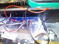
Can someone guess what happening?
Look att mosfet. Looks something is missing.
Attachments
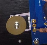
Yeah, I've been 'caught-out" like that before too - failed to make sure nothing in the threaded hole didn't later get pushed out and cut thru the insulating film - I now try to avoid it with transistor clips, bars, etc and as I tend to 'play' with the circuit board components more than once - an inveterate fiddler!
It does produce a uniform and consistent pressure between the transistor and heatsink but unsure if that's absolutely necessary for diy like this.
It does produce a uniform and consistent pressure between the transistor and heatsink but unsure if that's absolutely necessary for diy like this.
Thanks a lot for informations.
I must misunderstood for bulb tester.
The bulb keeps bright.
I have checked how trimpot works but possibly upside down.
I have set clockwise full. I will check it again.
I must misunderstood for bulb tester.
The bulb keeps bright.
I have checked how trimpot works but possibly upside down.
I have set clockwise full. I will check it again.
Attachments
- Home
- Amplifiers
- Pass Labs
- F6 Illustrated Build Guide