thx for the info...Hi,
you don't need the trim-pot. The gain is "fixed" with a normal resistor.
Regards
Johnny
regards
s.
Hi anyone, i need help on my build, regarding programming the uC board, i had successfully installed the v2.93 firmware on the uC board and im using the dual oled display but after installing the firmware, turned off, removed usb and P17 jumper then turned on, nothing happens, oled display does not turn on even i press the switch. also do i need to bridge the DSEL0 pads? or does it need to be connected to the left and right preamp card inorder to work? thanks to anyone who can help.
regards,
mj777
regards,
mj777
Hi Alex, i can upgrade successfully the firmware of the uC and when i turned off the main supply then turned on there is no light on the LED and no response when pushing the switch, i could have missed something i will try to check where the power is not going through.
Regards,
Marjohn
Regards,
Marjohn
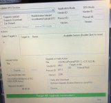
Attachments
Hi Alex, i can upgrade successfully the firmware of the uC and when i turned off the main supply then turned on there is no light on the LED and no response when pushing the switch, i could have missed something i will try to check where the power is not going through.
Regards,
Marjohn
Regards,
Marjohn
Hi Alex, i tried the older firmware version then the latest version And nothing change can not make it work. And if the LED is not turning on, does it mean that the stm32 is damage?
Regards,
Marjohn
Regards,
Marjohn
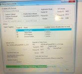
Attachments
Marjohn,
I am by no means expert here (I am sure Alex will confirm this...) but have you done some basic verification? Do you have +5V and +3.3V on respective pins of STM?
If LED does not light with low intensity (as it should in standby mode) after powering board I would think that there is something wrong with power supply or LED itself.
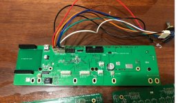
Can you also verify your LED connections? It is not 100% clear from pictures you have attached but seems that your LED wires (RED and BLACK?) are connected to PIN 1 and 2 of P4 and if this is the case this is not going to work. You should have cathode of LED connected to PIN 1 but anode should go to +5V (PIN 6)
Also - what type of encoder you have and have you stuffed your board according to particular type you have? Can you try without encoder connected at all?
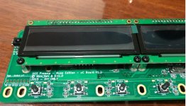
Next step I would think of would be to try without OLEDs installed - just to verify if you are able to toggle power by use of power switch which should be visible at LED intensity change.
Also, maybe it would be good idea to verify if redundant components you have soldered (I see that you have soldered T1 which is not used now) may have any effect.
Anyway - good luck and do not give up. Most probably your STM is ok (as you can program it) so there must be something else - maybe some wrong soldered PINs etc?
I am by no means expert here (I am sure Alex will confirm this...) but have you done some basic verification? Do you have +5V and +3.3V on respective pins of STM?
If LED does not light with low intensity (as it should in standby mode) after powering board I would think that there is something wrong with power supply or LED itself.
Can you also verify your LED connections? It is not 100% clear from pictures you have attached but seems that your LED wires (RED and BLACK?) are connected to PIN 1 and 2 of P4 and if this is the case this is not going to work. You should have cathode of LED connected to PIN 1 but anode should go to +5V (PIN 6)
Also - what type of encoder you have and have you stuffed your board according to particular type you have? Can you try without encoder connected at all?
Next step I would think of would be to try without OLEDs installed - just to verify if you are able to toggle power by use of power switch which should be visible at LED intensity change.
Also, maybe it would be good idea to verify if redundant components you have soldered (I see that you have soldered T1 which is not used now) may have any effect.
Anyway - good luck and do not give up. Most probably your STM is ok (as you can program it) so there must be something else - maybe some wrong soldered PINs etc?
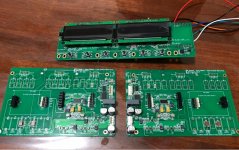
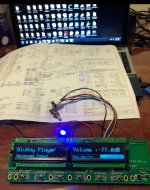
@Jacek_k_wawa, thanks a lot for all of your tips and advise, i finally made it work, you are right, it is on the type of encoder that i used, and the connection of the LED. Thanks again for the help that is highly appreciated.
Regards,
Marjohn
Regards,
Marjohn
Attachments
Last edited:
")
- Home
- Amplifiers
- Pass Labs
- UGS-muse preamp GB