Don't short the outputs. You may short the inputs, but you don't have to.
8 Ohm with 28V across them will dissipate just shy of 100W, so...
You could use a light bulb as a load if you really want to test the PSU. Otherwise I'd just confirm that the PSU puts out an unloaded voltage fairly close to the nominal design voltage and confirm principal operation of the frontend circuit with the bench supply. After that, do the rest (frontend bias, output stage bias) with the actual PSU or the settings will be meaningless.
When I build mine, I used to test the PSU with 8ohm 50W resistors, but didn't quite get the voltage drop as is the case with the finished amp. I have dual PSU, like you are planning and got an additional +/- 2V drop. As for your second question, when testing voltages, as per test sheet, before installing the VFET's, nothing is shorted.
Thanks guys. Beach this weekend, then I hope to get some progress. Setting up the front end with the bench supply will let me complete chassis construction after mounting the VFEts, and not going back and forth.
Hi!
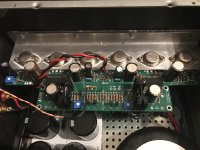
I up and running my vfet, it sounds very good.
But i missing gain it's huge different between my F5.
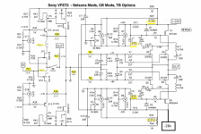
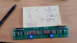
My build its based on Vfet r2 (teabag), the yellow is the diff, from the original.
I have the bias about 1,5 amp 54 celsius. The frontend is 1,8v.
The SW (feedback) is open, everything seems to be ok,
The problem is it decrease gain in the frontend.
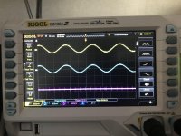
If you look at the picture from my oscilloscope.
The yellow is the input signal, 5,76 vrms, from the frontend (r20) 3,67 vrms.
")
I have switch closed and R46 open the problem still exist.
Tried a Sony TA 2000 preamp without success, tried with 100 db sensitivity speakers, no success.
If i get max output from preamp (Sony TA 2000)1V (Pre out), 2.5V (Pre out Max).
It play very low music.
If i use my ba-3 with cdplayer i got decent volume, if i had the ba-3 on max volume 100db speakers.
I don't really know how to start to fix this problem.
I have measured the bias, the frontend (1,8v) etc.
It seems that the input signal is decreasing.
Hope someone have some idea where to start to find this problem
Attachments
Last edited:
Okay, you now have the switch position jumpered, thus the feedback loop is always closed.
What value is R23? What value are R24 and R46?
R21 and R22 at the input slightly attenuate the input signal, changing R21 from 4k75 to 2k21 will only result in a 0.5dB difference.
I don't fully understand your measurements. What are you applying to the input? What appears at the output of the frontend over R20 (value?)? What appears at the output of the amplifier?
My resistor value is R23 4,75k,
R24 332 ohm
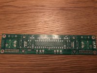
R46 dont exist see picture.
I applying a sinus curve 794 hz 5,76 Vrms on the input.
measure the output on the frontend R20 (marked out on the pcb) 3,67 Vrms
The last measurement is on the speaker connection 2,1 Vrms
R24 332 ohm
R46 dont exist see picture.
I applying a sinus curve 794 hz 5,76 Vrms on the input.
measure the output on the frontend R20 (marked out on the pcb) 3,67 Vrms
The last measurement is on the speaker connection 2,1 Vrms
Attachments
Last edited:
I have not followed your problem too closely so this may have been already addressed. It has been awhile since I built my V-fet but if I remember correctly the BC550 and BC560 pinout is different from the ones Nelson used. If so do not install them as per board but flip them.
The old ZTX/BC pinout mismatch, yes. But in this case I believe the pcb (dubbed AL at some point http://www.diyaudio.com/forums/blogs/tea-bag/352-sony-vfet-version-2-al-boards-build-blog.html) fits the BC pinout. Still, a valid concern and worth pointing out.
Edit: Congrats on finding the bug cosmo61! I'm looking forward to updates on your build!
Edit: Congrats on finding the bug cosmo61! I'm looking forward to updates on your build!
Attachments
Thank's for your time and effort!
I found the problem.
It was R22. I used a resistor 47,5 ohm instead for 47,5k ohm.
The input signal was really bad.
Been there, done that on other builds. Congratulation, enjoy.
Thank's for your time and effort!
I found the problem.
It was R22. I used a resistor 47,5 ohm instead for 47,5k ohm.
The input signal was really bad.
I don't think you can blow your JFEt's with R22 being 47.5 Ohm.
You are protecting the gates a bit too much
You have attenuated it to 1/100 of the original input signal.
- Home
- Amplifiers
- Pass Labs
- Sony VFET Amplifier Part 2