I have both amplifiers and:
- I "absolutely love" the SIT-2
- I "love" the VFET amp
I also own 4 the original Sony VFET amps and have collected them since 1978, always loved them but the SIT-2 is entirely different. For lack of better expression, the VFET amp has an ultrasonic characteristic that is unlike any other amp I own or have listened to, the SIT-2 may be slightly less detailed but it is simply magical with my Altec Valencias!
Armin
Push pull vs SE, personal preference. Much the same with tubes, push pull vs SET. I enjoy both sounds depending on music. I have a friend that owns the SIT-2 and has built and owns a V-fet. He has said much the same as you. I heard some Valencias years ago. Fantastic sounding horns. I own modified Klipsch Lascalas.
Last edited:
Hi Everyone,
i'm hoping for some help with my problem. This spring I built the DIY Sony VFET, one channel worked perfectly the other not. The bad channel appeared to bias up correctly and all voltages were the same as the good channel, both channels played at very low volumes, but when the volume was increased the bad channel would just fade out. When the bad channel fades the voltage on T18-gnd goes from ~ 200 mV to ~ 26 V. I triple checked all of the resistors, everything was correct, all transistors were in the correct spots. Thinking is was a problem with the input section I replaced the input jfets with a net set from the DIYAUDIO store and Q3/Q4, and reflowed the board. didn't find any bridges, or cold joints. Still had the same problem. After that I put the project aside for a while. Now I have a little free time I'd like to try to get it going. Today I dusted it off and did a continuity check and compared the results to the good board everything was identical except that Q2 showed continuity between the drain and source (outer legs) on the bad board, and not on the good one. I have enough spares to replace all of the regulators and transistors with the exception of the 2SK82/2SJ28, so if their bad I'm out of luck. My plan moving forward was just to replace the regs and to see where I land, and if that doesn't do the trick replace all of the other transistors. But the Q2 continuity has me wondering. Before I rip everything apart I was hoping some of the more experienced members might have some ideas that could help point me in the right direction.
Thanks,
Paul
PJN,
I had this problem on one of my builds and it’s was just that the bias on the second stage drifted with temperature. Let the amp warm up for an hour then recheck all the bias test points they will drift with temp. Re bias and then let the amp cool down and then re test once it’s back up to temp.
My two cents....
You will be happy to know that this is a reliable seller, and he also has the
Tokin THF-51S, which is a similar part.
i have ordered a pair of this THF51-S what is the usual operating point for these is it the same as the 2SK82 20V 2A ? or is it better with high voltage or high current?

thanks
Hi Juanitox. I did time ago. Really liked a lot. I did with ccs, inductor and resistor loads. For me, the better was with resistor. With inductor sound was a little dark, fuzzy, compared with resistor. But if you want get the most output possible, I used around 80V PS and almost 4A of quiescent current. Dissipation was enormous, but sound wonderful...
Try it.
Best
Try it.
Best
Yes, with these parameters I got around 18w at 8ohm. But you can try others points. Your speaker is the key factor. For me, now, with two or three watts are enough and low PS values are enough. When I built this monster, I want to search for limits (and it is not equal two watts with amp with only two watts that two watts with very big amplifier). Distortion figures are similar at maximum power (2 or 18 watts), but at 2 watts are better with bigger amps (distortion numbers).
I built other version with only 6 watts lowering PS, and soundwas wonderful too.
Try it...
Good luck
I built other version with only 6 watts lowering PS, and soundwas wonderful too.
Try it...
Good luck
i have ordered a pair of this THF51-S what is the usual operating point for these is it the same as the 2SK82 20V 2A ? or is it better with high voltage or high current?
Only a quick test, but I found it fairly similar to 2SK180/182. You could sub
it right in. Vgs figures on all these require individual adjustment.
Self Bias
Hi Juanitox
Wonder why you are wearing mask, don’t smoke your THF-51S, just applying a negatively gate bias before power on your circuit.
One member of our forum, gantez,went further by never switch it off his or her “SIT 2SK82 Cyrclotron Power Buffer” bias circuit (sorry no book marked, please use forum’s search function)
I use a simple and safe approach by lifting the source differencce potential up with an 1 Ohm resistor and my gate is leveled to the other end of that resistor, with that level shifting, i got a - 2.7v to the gate.
Well, I run my THF-51S pair from 12v to 35v with that 1R resistor, I found no change in gain, minuscule change in second harmonic level and large swing in third harmonic ( a push pull balanced circuit).
Have fun and always bias it first.
thanks juma the goal is to drive a pair of Altec 414A so i don't really needs big watts just good ones
to begin with something safe what is the voltage needs on the gate to get 2Amp with the THF51s i plan to use a source resistor at first.
Hi Juanitox
Wonder why you are wearing mask, don’t smoke your THF-51S, just applying a negatively gate bias before power on your circuit.
One member of our forum, gantez,went further by never switch it off his or her “SIT 2SK82 Cyrclotron Power Buffer” bias circuit (sorry no book marked, please use forum’s search function)
I use a simple and safe approach by lifting the source differencce potential up with an 1 Ohm resistor and my gate is leveled to the other end of that resistor, with that level shifting, i got a - 2.7v to the gate.
Well, I run my THF-51S pair from 12v to 35v with that 1R resistor, I found no change in gain, minuscule change in second harmonic level and large swing in third harmonic ( a push pull balanced circuit).
Have fun and always bias it first.
Attachments
thanks , to resume the THF51s will accept nearly the same as the 2SK180
( let say betwween 30/40V 2amp )
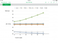
1: 1x300W 120V bulb
2: 1x 300W 20R resistor
3 the Hammond 193V choke
4: CCS with IXFN140N20P Mosfet like the 2SK77B 50W amp of mr Pass
hard to choose ( except the Choke load for saving the planet )
( let say betwween 30/40V 2amp )
1: 1x300W 120V bulb
2: 1x 300W 20R resistor
3 the Hammond 193V choke
4: CCS with IXFN140N20P Mosfet like the 2SK77B 50W amp of mr Pass
hard to choose
( except the Choke load for saving the planet )- Home
- Amplifiers
- Pass Labs
- Sony VFET Amplifier Part 2