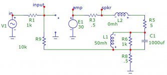
Hello Soundhappy. The left schematic in your post is for a like-diyF5 which is configured [at its power output] as a Current Source Amp driving a full range loudspeaker. The schematic on the right is like that of diyF5; namely a Voltage Source Amp. Both schematics and their amps "respect" and stay away from the sensitive commercial nature of F7.
If you parse that article carefully from a technical standpoint, it comes
out flawed.
I have pointed out elsewhere that pcf didn't go very far back then mostly
because the bandwidth of their equipment was poor and they looked to
be trying to achieve the wrong things. But then this was 1957...
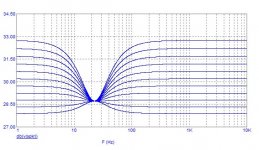
You can plug a simple pcf circuit into a simulator and get some very
interesting stuff. Here is the frequency response of an amplifier driving
a simulated speaker with varying amounts of pcf, and this doesn't
begin to address the control offered by a negative damping factor.
Attachments

A suggested experiment..
A subtle yet a powerful attribute is present in power amps like F7; because they use positive feedback [PF]. The woofer in a multi-way loudspeaker is mostly affected by it. This [or your] loudspeaker may be put in the corner of the listening room; so as to simultaneously play music and to also attenuate standing waves. This power amp-woofer combination [of your loudspeaker] is expected to perform like that of the device described by Pass in his Patent US 4,899,387. His device essentially uses [PF] to attenuate the abundant standing waves in the corners of the listening room which normally corrupt the accuracy of the reproduced music inside it.
The suggested experiment is to relocate your stereo loudspeakers to the corners and angle them to get a sweet spot like you've already done for their current location etc.. And please post the resultant experience. This experiment is reversible as the loudspeakers will readily go back to their original location if you dislike the outcome!
By the way, I am practicing the above suggested experiment; e.g. as I described in the last couple of posts in the thread "DEF Amp".
Best
Anton
Antoine, would you say that PCF is acting against back EMF ,like reducing it , especially on large speakers ?
.
If you want to talk about back emf and how speakers behave with current drive vs voltage drive, that should at least be a separate thread if not in one of the other forums.
I have measured a driver's distortion with a current amplifier and a voltage amplifier. The current drive amp has measurably less distortion. Whether this sounds better or IS better in some subjective way, is up to the individual.
I would not pollute this thread with a long, drawn out discussion which this sort of discussion would certainly be.
The speaker produces distortion in either the amplifier current or the amplifier voltage depending on whether the amplifier is forcing voltage or forcing current. I have taken oscilloscope shots of current and voltage for both cases and measured distortion at the same time.
The reduction in distortion was not large enough to make it an earth shattering discovery. I think that you would get far greater reduction in distortion by using a push-pull electrostatic speaker instead of a voice coil + magnet speaker.
....You can plug a simple pcf circuit into a simulator and get some very
interesting stuff. Here is the frequency response of an amplifier driving
a simulated speaker with varying amounts of pcf, and this doesn't
begin to address the control offered by a negative damping factor.
Excellent Mr Pass

Thanks for the simulation schematic and interesting lesson
")
Thank you fabrice63 and woofertester for your posts. Hopefully the suggested experiment will fruit beneficial experiences.Antoine, would you say that PCF is acting against back EMF ,like reducing it , especially on large speakers ?
.
Best
Anton
Hello Soundhappy. The left schematic in your post is for a like-diyF5 which is configured [at its power output] as a Current Source Amp driving a full range loudspeaker. The schematic on the right is like that of diyF5; namely a Voltage Source Amp. Both schematics and their amps "respect" and stay away from the sensitive commercial nature of F7.
Great Antoinel!
Yes F7 has this similar to F5 "style" minimalistic amp construction: semiconductors and resistors in the signal path without cap's.
Innovate Mr Pass touch is for the first time Latfet's sings with new voice highly stimulated by pcf like not in any others amp's.
Signed Papa aficionado and hobby amateur

Congrats Nelson on the great review of the F7!
I am currently waiting for boards from the DIY audio store for the F5 and cannot wait...
I have read this thread with people trying to reverse engineer your F7. I have had a play with LTspice, but wont post if its frowned upon.
I am currently waiting for boards from the DIY audio store for the F5 and cannot wait...
I have read this thread with people trying to reverse engineer your F7. I have had a play with LTspice, but wont post if its frowned upon.
- Home
- Amplifiers
- Pass Labs
- First Watt F7 review