regarding harmonic's phase , all you need is to read *.log file of LTSpice simulation
I have FFTChart proggie which is useful for translating log file to graphs , but it refuses to open them lately , otherwise I would post screenshots here
however , as always , I made one channel mockup on my regular Papamp test bed (MDF plate, big chunk of Al, two Spragues , big Donut) , with 2SJ56/2SK176 in output
it's fast and punchy , with deep bass and nice rest
not able to make measurements right now ...... and probably will not , especially because Papa already made them
conclusion - fun amp
go and build it - if not all , but almost all breadcrumbs are there
I'm not interested in LTspice simulation results, I just want to know if the observation on an oscilloscope showing the residual waveform can easily be characterised as positive phase or negative phase 2nd harmonic in the same manner shown by the simulated results previously posted, or whether that was just a coincidence.regarding harmonic's phase , all you need is to read *.log file of LTSpice simulation
however , as always , I made one channel mockup on my regular Papamp test bed (MDF plate, big chunk of Al, two Spragues , big Donut) , with 2SJ56/2SK176 in output
This is a two way street you know.
We want to see porn.

This is a two way street you know.
We want to see porn.
naah
considering waste number of parts , I would reveal too much of Real McCay
so , no porn
naah
considering waste number of parts , I would reveal too much of Real McCay
so , no porn
I thought it was already pretty obvious what the end schematic looked like, however with what has been happening on ebay (cloning galore) it's probably wise to keep it private.
you know that I'm lately veeery reluctant in threads like this one , from two reasons :
- acting secretly I'm looking much smarter than I really am ,
- not wanting to reveal what Papa didn't reveal (I know he deliberately is spilling breadcrumbs , but he's also keeping real schematic as secret , certainly from anti-theft reasons)
- acting secretly I'm looking much smarter than I really am ,
- not wanting to reveal what Papa didn't reveal (I know he deliberately is spilling breadcrumbs , but he's also keeping real schematic as secret , certainly from anti-theft reasons)
And I agree with you ZM
One single slip and eBay would be full of every possible option from boards to "Kits"; the cost + time involved in stopping this would be prohibitive.
On the assumption that NP is unlikely to change his philosophy, we can be sure that more will be revealed when the time is right [].....it is said that patience is a virtue!!
As for you saying that you may appear more knowledgable than you are, I have to say that in this department that is modesty in its extreme.

One single slip and eBay would be full of every possible option from boards to "Kits"; the cost + time involved in stopping this would be prohibitive.
On the assumption that NP is unlikely to change his philosophy, we can be sure that more will be revealed when the time is right [
].....it is said that patience is a virtue!! As for you saying that you may appear more knowledgable than you are, I have to say that in this department that is modesty in its extreme.
go and build it - if not all , but almost all breadcrumbs are there
Amen to that, for those keen on it
Sorry for sidetracking the thread a bit.
The amp looks pretty simple and the conceptual schematic and architectural description/references along with the owner's manual itself give away enough for those interested. Hope to read the reviews soon!
As for you saying that you may appear more knowledgable than you are, I have to say that in this department that is modesty in its extreme.
Sorry Zen Mod you've lost the title of being the dumbest.
Hahahaha

Oops:
I just discovered that my circuit in post #143 when tuned to obtain the F7.pdf specifications has a problem: The input impedance is -10K Ohms.
Oops!
I have another circuit that appears to work that has an input impedance of +10K Ohms and otherwise behaves properly, but suffers from a different issue: neither terminal of the speaker load is connected to ground. I guess that isn't really a problem since balanced (bridged) amplifiers have the same issue.
I will show that circuit after I am convinced it doesn't have other issues.
.......neither terminal of the speaker load is connected to ground. ........
well , it needs to be , just for idiots
I'm always observing/treating output terminals as "don't connect these to gnd,just to speakers!"
yup , that's after years of service work and just one instance of burned amp fuses , when I connected scope probe backwards .
after that , my scope is lifted from safety gnd , just in case
(and yes, I'm obtaining safety in other ways)
But do not oscillate!I want to give you all positive feedback!
I really enjoy to learn by your puzzle steps!
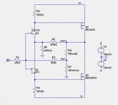
Here is another try at the schematic which now has a +10k Ohm input impedance and otherwise good specifications when populated with the right resistors and fets.
The only issue is possible sensitivity to noise on the speaker outputs. Perhaps this is the issue Nelson addressed with this comment in F7.pdf:
The only issue is possible sensitivity to noise on the speaker outputs. Perhaps this is the issue Nelson addressed with this comment in F7.pdf:
Also, I put more capacitance in the power supply and found a clever way to further reduce the effect of high frequency DAC noise and environmental RF.
Attachments
Here is another try at the schematic which now has a +10k Ohm input impedance and otherwise good specifications when populated with the right resistors and fets.
The only issue is possible sensitivity to noise on the speaker outputs. Perhaps this is the issue Nelson addressed with this comment in F7.pdf:
Hello lhquam.
Does/should your diyF7 circuit invert phase at its power output?
The 10K input impedance suggests that the gates' joint node of the front end JFets is a virtual ground [VG]. VG was derived when two independent signals [one from input and the other from power output] merge such that they are out of phase and mostly equal in amplitude. It follows that R2 in your schematic is equal to 47K to give~ X5 gain like the spec. of F7 given by Mr. Pass.
Hello lhquam.
Does/should your diyF7 circuit invert phase at its power output? The 10K input impedance suggests that the gates' joint node
of the front end JFets is a virtual ground [VG]. VG was derived when two independent signals [one from input and the other
from power output] merge such that they are out of phase and mostly equal in amplitude.
It follows that R2 in your schematic is equal to 47K to give~ X5 gain like the spec. of F7 given by Mr. Pass.
It's non-inverting, so the R2 would be the positive feedback resistor. For a gain of five, R5 = 100, and R6 = 25, for example.
Last edited:
- Home
- Amplifiers
- Pass Labs
- First Watt F7 review