A fellow member asked me if this preamp can be made with simple BJTs only so I gave it a try and it works lovely.
He is OK with max. 6V_RMS at the output so the rail voltage is down to 24V.
Since the use of a BJT at the input and single rail PSU imply the use of an input cap I introduced local Schade feedback (R10, R3) to control the gain (about 13dB). Z_out is a bit higher (150-200 R) , Z_in too (47k), some elements' values are changed, but it still sounds very good...
Hello Juma,
can you tell me where to put the volume pot in the schematic built with bjts?
Will a 10k pot be ok?
Thanks,
Ulf
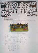
I've been doing some more work on this circuit to improve further it's sound and characteristics.
Now the feedback loop is gone and the input impedance is much higher (about 680k) while the Zout is still low (less than 50 R). The gain is about 14 dB and it depends on R4 and R13. R4 degenerates the JFET and R13 loads the gain stage, so more load (lower value of R13) and/or more degeneration (higher value of R4) means less gain, and vice versa. Practical values would be 1k5/680R for about 6dB gain and 3k9/330R for about 20dB.
Power supply voltage is somewhat higher (40V). Max output is about 9V_rms at 10k load. Current consumption is about 11mA and it depends on BF862's Idss. If your BF862 has Idss higher than 16mA make R3=10 R or so. The input cap is introduced (I use WIMA MKC) because JFET's gate sits at about 6V but since it is of a small value it's not of a great importance.
Attachments
Hello juma, just want to say thanks for the update! I have been looking at this design for a while now, and plan/hope to build it during winter. Seems like a nice simple circuit for a novice like me ")
A question regarding power supply please: Should I even be thinking about a regulated supply for best performance, or is the PSRR so high that a simple CRC setup will be sufficient? (Is this where the Gyrator does its bit?..) - Do you still use the Smps based solution?
Edit: Perhaps I should rather ask if you use the capacitance multiplier mainly because of the Smps? Would you still use it with a regular toroidal transformer based power supply?
Your work and contributions is much appreciated
Last edited:
Hi jvhb,
I used an SMPS in previous version just because I had it handy and the voltage was suitable but I prefer a nice linear PSU, from reasons which I'll bring out if you open the separate thread about it.
For the circuit in post #24 I use 10VA 2 x 18V~ transformer with secondaries connected in series which gives about +50V after rectification. The simple regulator follows - same as usual MOSFET cap multiplier with a small addition: 3 x 15V zeners connected in series, from gate to ground and a 5mA CCS from drain to gate to feed the zeners. That gives about +41V at the source pin.
So yes, a nice clean PSU is always beneficial. Since the current consumption is in this case low it would be easy to do some shunt reg or anything else that one likes...
Thanks for the offer regarding seperate SMPS thread, but lets leave it for now: I am not interested in using SMPS, for the simple reason that I prefer to build with technologies/topologies that I more or less understand. And SMPS I will never really grasp, and much less be able to service or repair . So I will stick with linear PSU in any case
I have been reading up on capacitance multipliers (which I have not made or used before), and the principle seems quite clever and not too complicated. Made me wonder why I don't see them used more? I would imagine there is an ongoing debate on capacitance multiplier vs. very large capacitors - and which solution "sounds" better..
But I might start with a simple CRC(RC) layout, and then add/try out cap. multiplier and (shunt?)regulation at later stage. Or why not a Gyrator combined with cap. multi! (or is that not a good idea?). BTW: I am not really expecting answers to the above, as it would also be a topic for a another thread..
A philosophical sidebar: As many other novices in audio electronics, I probably tend to focus too much on the PSU, and not enough on the actual amplifier topology and design. I think the simple reason for this is that PSU design seem easier to understand. In the same manner, people with even less (or no) grasp of electronics, will often focus all their attention on (overpriced) cables and such.
What I would really like to hear your comments on, is how this latest design compares to the old version, and also how it is conceptually different from the BOZ preamp?
Is one better than the other, or are they just variations on the same principle? I have been comparing the schematics, but can't really follow or fully understand what is going on.
I saw another thread regarding the use of ZV9 layout as preamp, and Nelson responded by indicating that the use of a single JFET was not actually so good: http://www.diyaudio.com/forums/pass-labs/83462-zv9-preamp.html (Read just the first two posts)
- What is your view on this?
And please don't say I should just build both BoZ, BoSoZ and Gyrator ZV9 based pre (and why not BA3-FE and Pumpkin also), and simply compare the sound! -I may eventually do just that, but all these things are very time consuming, and we can't always build or test all we would like to..
As you may have gathered by now, I am trying to learn this stuff (as much as possible anyhow), and not just blindly follow a recipe
. So I will stick with linear PSU in any case I have been reading up on capacitance multipliers (which I have not made or used before), and the principle seems quite clever and not too complicated. Made me wonder why I don't see them used more? I would imagine there is an ongoing debate on capacitance multiplier vs. very large capacitors - and which solution "sounds" better..
But I might start with a simple CRC(RC) layout, and then add/try out cap. multiplier and (shunt?)regulation at later stage. Or why not a Gyrator combined with cap. multi!
(or is that not a good idea?). BTW: I am not really expecting answers to the above, as it would also be a topic for a another thread..A philosophical sidebar: As many other novices in audio electronics, I probably tend to focus too much on the PSU, and not enough on the actual amplifier topology and design. I think the simple reason for this is that PSU design seem easier to understand. In the same manner, people with even less (or no) grasp of electronics, will often focus all their attention on (overpriced) cables and such.
What I would really like to hear your comments on, is how this latest design compares to the old version, and also how it is conceptually different from the BOZ preamp?
Is one better than the other, or are they just variations on the same principle? I have been comparing the schematics, but can't really follow or fully understand what is going on
.I saw another thread regarding the use of ZV9 layout as preamp, and Nelson responded by indicating that the use of a single JFET was not actually so good: http://www.diyaudio.com/forums/pass-labs/83462-zv9-preamp.html (Read just the first two posts)
- What is your view on this?
And please don't say I should just build both BoZ, BoSoZ and Gyrator ZV9 based pre (and why not BA3-FE and Pumpkin also), and simply compare the sound!
-I may eventually do just that, but all these things are very time consuming, and we can't always build or test all we would like to.. As you may have gathered by now, I am trying to learn this stuff (as much as possible anyhow), and not just blindly follow a recipe
Exactly... I am not really expecting answers to the above, as it would also be a topic for a another thread...
Absolutely. And that is good so - everybody should have fun on the level they choose..... In the same manner, people with even less (or no) grasp of electronics, will often focus all their attention on (overpriced) cables and such.
I don't publish stuff that doesn't sound better (to me) than known equivalents....Is one better than the other...
I didn't read that. I read that differential cascoded JFETs sounded better to Mr Pass than single cascoded JFET. There is no schematic, no other data to make a sensible comparison, so I can't comment on that, except that there is a noticable difference in this circuit between BF862 and 2sk170. There is also a difference between CCS and gyrator, so there is no chance for apples to apples comparison...... Nelson responded by indicating that the use of a single JFET was not actually so good: http://www.diyaudio.com/forums/pass-labs/83462-zv9-preamp.html (Read just the first two posts)
- What is your view on this?
That's exactly what I do. I like prototyping and testing/listening to diverse circuits, playing with them and changing them the way they sound better (to me). I don't have an agenda here, I sell nothing, not trying to prove anything, just doing what I like and sharing the results ....... And please don't say I should just build...
Alright fair enough.. I certainly didn't mean to imply that you had any sort of "agenda", I was simply interested to hear your views on these different variations of single ended preamp topologies
Have you had a chance to do any type of distortion measurements on your design?
I have actually had most of the parts for a BA3-FE sitting around for a while now (too long!). But it looks like your design may end up being built first, as I feel it should be simple to do on perf-board - and Reichelt.de has all the (cheap) components
So I might be able to do a comparison of those two during the winter (if all goes well..)
-Almost forgot: Wima MKC are not available. Do you think MKS-4 will work ok instead?
-Almost forgot: Wima MKC are not available. Do you think MKS-4 will work ok instead?
Have a look:
MKC4 0,047U 250V
I didn't think you did. It's just that when it comes to comparing different stuff, things tend to quickly become more complicated than I like them to be....... I certainly didn't mean to imply that you had any sort of "agenda"...
If you mean measuring a harmonic content of the single tone signal, I don't do that any more - I found that it's a too shallow approach when it comes to evaluating the way circuit reproduces the music.... Have you had a chance to do any type of distortion measurements on your design? ...
I often visit live acoustic performances and have a pretty good idea how instruments and orchestra should sound and that's my measure.
Of course, anyone is free to choose his own way to evaluate the quality of any circuit.
If you can't find MKC caps and look for an alternative I can tell you that I prefer WIMA MKP-10 over MKS-4.
Thanks for the tip nr12! I didn't know that shop.
But since MKC are EOL, I guess the question is, if there are any objective reasons to prefer them over MKS? Should I buy a bunch of MKC while I can still get them? Are they actually better than MKS (for this type of application), or is it more a case of some audiophiles seem to hear a difference?..
Edit: Hadn't seen latest post from juma when composing this. Will have a look at MKP-10. They are cheap, so might as well get some of each type. Question regarding MKC still valid though - is there some special "magic" to these? Funny how many of the best parts for audio seem to be EOL
Last edited:
MKC are both subjectively and objectively really good. You can find more than a few papers with measurements. And all of those caps are cheap enough to try them personally and see what you like the best.
If you define magic as art of illusion and accept that there is some illusion involved in a way that our brains process information delivered by ears, then you will agree that it is OK to use funny words to describe phenomena that are not measurable, yet clearly present. And caps are not among them
If you define magic as art of illusion and accept that there is some illusion involved in a way that our brains process information delivered by ears, then you will agree that it is OK to use funny words to describe phenomena that are not measurable, yet clearly present. And caps are not among them
Music can definitely be magical, but regarding electronic components I like to base my decisions on science if possible
A couple of questions if you have time:
Regarding the C3 output cap: why so large? Do you have a power amp with unusually low impedance? Even for 40k input impedance, 2uF should be fine (-3 db point at 2hz). Or am I missing something?..
Regarding voltage swing: If I wanted a bit more in reserve, could I increase rails to 50V without any other changes? (While keeping an eye on power dissipation of transistors).
Thanks
10k is not an unusual input impedance in the world of amplifiers and 10u is just OK in such a case. Coupling cap is not only about freq. response but also about phase shift it might bring in. And that can be clearly heard.
Changing the PS voltage to +50V for the circuit from the post #24 is not trivial. Besides recalculating the voltage divider values, more powerful cascode BJT had to be used which means upsetting a few parameters. Small MOSFET could be used in that position too but a change like that needs prototyping a new circuit and testing its performance too.
Changing the PS voltage to +50V for the circuit from the post #24 is not trivial. Besides recalculating the voltage divider values, more powerful cascode BJT had to be used which means upsetting a few parameters. Small MOSFET could be used in that position too but a change like that needs prototyping a new circuit and testing its performance too.
I must say I a surprised this has replaced the LSK. I have listened to the LSK quite a lot recently with an INT30a, with the gain cut back to 10, and consider it to be pretty neutral. Does this amp add a touch of warmth? Have you considered the possibility of a CCS fed Vref for the gyrator? Gonna try such a beast feeding LED's for a tube preamp. Morgan Jones showed it to be quite low noise and its pretty to boot. I may have to try this simply because it replaced LSK and is simple. One quick question. I assume the 47uF elco on the other side of R13 is to keep the signal from leaking out the wrong end?
Would raising the reflected impedance of the Vref, by changing it to a CCS based option, allow for smaller coupling cap to the upper, active load? Also, if you haven't tried them, organic polymer caps make nice bypass caps. If you get the itch, try one on the Bjt reference.
- Home
- Amplifiers
- Pass Labs
- Gyrator loaded Son of ZV9/F3