I have just finished my DAC AD1865, put an order for Alpair 10P, but Amplifier is still on progress to make UMS on 4pcs heatsink, need to find CNC shop.
But i still have a missing link, which i'm not sure it's missing or not. Related to several post on gain matching, my question will be specific to only PaPa amplifier which I only want to build. Below my situation:
- my dac output voltage based on designer calculation should be around 3.6Vrms (I'm still finding a way on how to measure it, i only have dmm)
- amplifier module/parts that is completed : SIT L'Amp and AlephJ (F6, F4 and F5 will be on my next list).
- as far as i know, from above amplifier list, I can separate them into 3 groups
1. High gain amplifier (no need extra gain from preamp) : AlephJ & F6
2. Middle/Low gain amplifier (need extra gain from preamp) : SIT & F5
3. Amplifier without voltage gain : F4
- what I'm thinking for the solution on above 3 groups:
1. Use passive (potentiometer only) or build buffer (my DCB1 build did not succeed, never been able to fix it's shunt)
2. Use middle gain preamp : I already build amb headphone amplifier (α20 powered by σ22) with gain 6
3. Use high gain preamp : i'm thinking of BA-3 FE
Instead of 3 separate preamp, is there any diy preamp design with variable gain? This TKD selector switch will be a nice item to have. I rarely see this variable gain option on diy design, but you can find it in commercial product (which i dont have any interest to buy it)
ps : english is not my native language, hopefully above summary is understandable.
there is no so versatile DIY preamp around , marrying two things - wide range of possible gain (and output swing!) and painless switched gain ratio transition - without need to readjust output offset (or at least output node voltage potential)
my is more than capable regarding gain and swing but , as long I'm not implementing offset servo subcircuit , you can't simply switch feedback ratio - to change overall gain
my
is more than capable regarding gain and swing but , as long I'm not implementing offset servo subcircuit , you can't simply switch feedback ratio - to change overall gain... Instead of 3 separate preamp, is there any diy preamp design with variable gain?...
Sure, I'm testing the prototype now - the complete build with pics will follow.
The input is low-noise, high gm, current production JFET (BF862) cascoded with BJT (if you can remember, it's the "modulated cascode" from F3). This gain cell is loaded with BS170 made gyrator (basically it's a choke with no wire and no iron).
The current through this SE preamp is about 10-12mA, it's set by R4. The gain is set by R16/R10 (6 dB) or R11/R10 (23dB).
The preamp will swing at the output more than 20V_peak (more than needed to drive F4 to full power). Zin is roughly 10k and the Zout is less than 50R (R12 included) so it will drive successfully even F4 without its input buffer.
BC547C has max. Vce of 45V, the BC546B is better choice.
The BJT and BS170 should be equiped with small TO-92 heatsinks (or a piece of copper foil) - they reach about 70 degrees C. I tried different devices - 2sk2013 instead of BS170 is good but with doubled Id, and IRF610 is not good even on cascode duty.
Listening to this pre, it has that nice F3-like "velvety" quality, but with no "darkness" and no impotence - very lovable. Still testing the addition of LATFET SF for a complete amp...
Attachments
Last edited:
That's impresive Juma, i cant wait for final version, pcb with transistor kit 
i have some question:
- any reason why using high voltage supply? Am i correct that all component from +55 until C5 are regulator? What is the voltage on C5?
- instead of only gain 2 and 15 options, what about additional options such as gain 1, 2, 4, 6, 8,15. wouldn't it be nice?
i have some question:
- any reason why using high voltage supply? Am i correct that all component from +55 until C5 are regulator? What is the voltage on C5?
- instead of only gain 2 and 15 options, what about additional options such as gain 1, 2, 4, 6, 8,15. wouldn't it be nice?
That won't happen, I don't have enough free time for such an enterprise...That's impresive Juma, i cant wait for final version, pcb with transistor kit
If you want enough output voltage to drive F4 to full power (40V peak-to-peak) it has to come from somewhere. Anyway, 55V is not high voltage - I got it from 2 x 12V AC transformer and voltage doubler...- any reason why using high voltage supply?
Yes, Q4 and surrounding parts form a capacitance multipler.Am i correct that all component from +55 until C5 are regulator?
About 53V.What is the voltage on C5?
Sure, you can do it with 6-position switch where each position will engage different resistor. But I wouldn't do that - it's only 6dB between positions and 6dB is just 2 clicks on the usual 24-position volume attenuator. So high gain/low gain switch makes most sense or you'll be using your volume attenuator in a very narrow range ...- instead of only gain 2 and 15 options, what about additional options such as gain 1, 2, 4, 6, 8,15. wouldn't it be nice?
Last edited:
I have just finished my DAC AD1865, put an order for Alpair 10P, but Amplifier is still on progress to make UMS on 4pcs heatsink, need to find CNC shop.
But i still have a missing link, which i'm not sure it's missing or not. Related to several post on gain matching, my question will be specific to only PaPa amplifier which I only want to build. Below my situation:
- my dac output voltage based on designer calculation should be around 3.6Vrms (I'm still finding a way on how to measure it, i only have dmm)
- amplifier module/parts that is completed : SIT L'Amp and AlephJ (F6, F4 and F5 will be on my next list).
- as far as i know, from above amplifier list, I can separate them into 3 groups
1. High gain amplifier (no need extra gain from preamp) : AlephJ & F6
2. Middle/Low gain amplifier (need extra gain from preamp) : SIT & F5
3. Amplifier without voltage gain : F4
- what I'm thinking for the solution on above 3 groups:
1. Use passive (potentiometer only) or build buffer (my DCB1 build did not succeed, never been able to fix it's shunt)
2. Use middle gain preamp : I already build amb headphone amplifier (α20 powered by σ22) with gain 6
3. Use high gain preamp : i'm thinking of BA-3 FE
Instead of 3 separate preamp, is there any diy preamp design with variable gain? This TKD selector switch will be a nice item to have. I rarely see this variable gain option on diy design, but you can find it in commercial product (which i dont have any interest to buy it)
ps : english is not my native language, hopefully above summary is understandable.
While I am sure Juma's preamp would be excellent, I would just put the B1 in front of a BA3 using the pot on the B1 to drive the BA-3 and then the power amp. Some kind of switch to take the BA-3 out of the path for passive use would be needed. I think the BA-3 would work fine as both your "medium" gain and "high" gain preamp. It can be configured for less gain if you desire.
Honestly, I would just use a BA-3 for all. Maybe a switch in the BA-3 to just use the vol pot in front of an amp as a passive solution is all that's needed. I know the F5 doesn't really need a buffer in front of the amp...not sure about the F6 or Aleph.
Yes it would - choose one with Idss in 12-15mA range.... Would 2sk363 be a good part to use if one has difficulty working with SMT components (BF862)? ...
It has somewhat higher gm and higher parasitic capacitances, but it's not a deal breaker...
Yes it would - choose one with Idss in 12-15mA range.
It has somewhat higher gm and higher parasitic capacitances, but it's not a deal breaker...
Thanks. I'll get a few BF862 to see if I can work with them. I assume one would also want to select parts in the 12-15mA idss range?
Cheers,
Dennis
Almost all that I've got (500 pcs.) are in the 13-14mA Idss range so I guess it's to be expected. Anyway, the datashet says that maximal Idss for this part can reach 25mA. Practically, it's OK too, the only concern would be higher current consumption i.e. higher disspation in cascoding BJT and gyrator MOSFET. JFET's disspation will stay low because it's limited by low Vds (about 3.5-4V)... I assume one would also want to select parts in the 12-15mA idss range?...
as a reminder, nothing beats the venerable AlephP in terms of ease of gain adjustment (a simple pot). with film caps all over it there is no issue with DC offset resetting. it can also handle both balanced and unbalanced signal; (granted that when used unbalanced it is sort of "underutilized" and for the cost of large film caps probably not the best choice). the swing is decent but probably 6dB short of driving F4 to full power. just like ZenM stated: there is no catch all choice .
>on the subject though of bf862 based preamp as often engineered by Juma: I was so impressed with the 8-9dB-gain preamp he proposed before for adding to F5, (it measured so clean and the gain held up steady to almost 200kHz), that I decided to make an 8-channel preamp this summer with R2R attenuators for SE use in multiamped systems. (too bad this little jfet does not have a complimentary pair!?). also important for me: my pcb is designed as mirrored image with all tall parts on one side and two stack up face-to-face with 1inch standoffs in b/ween for minimum package space (this makes for 4 channels already). I can show you pics in a few months. I can make the gerber file available to any member with a history on the forum if for DIY only.
http://www.diyaudio.com/forums/pass-labs/254190-best-options-making-f-5-integrated-amp-3.html#post3968949
.>on the subject though of bf862 based preamp as often engineered by Juma: I was so impressed with the 8-9dB-gain preamp he proposed before for adding to F5, (it measured so clean and the gain held up steady to almost 200kHz), that I decided to make an 8-channel preamp this summer with R2R attenuators for SE use in multiamped systems. (too bad this little jfet does not have a complimentary pair!?). also important for me: my pcb is designed as mirrored image with all tall parts on one side and two stack up face-to-face with 1inch standoffs in b/ween for minimum package space (this makes for 4 channels already). I can show you pics in a few months. I can make the gerber file available to any member with a history on the forum if for DIY only.
http://www.diyaudio.com/forums/pass-labs/254190-best-options-making-f-5-integrated-amp-3.html#post3968949
Last edited:
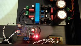
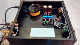
finally yesterday I finished my dfb1 using LT1084/1033 regulator, powered by 2x18V transformer. volltage out is set to 10.5V on both + and -. buffer board is still using teabag pcb but without salas shunt. i have prepared an area for ba3-fe or juma preamp pcb if extra gain needed someday.
configuration : qls qa550 -> ad1865 -> dcb1 -> gainclone mauro penasa -> 3way floorstand rated at 88dB 4ohm. they are placed on my bedroom 4mx3m
at this time i dont need extra gain from preamp. at night listening, potentiometer is set to 9 o'clock, measured 78dB on average and 82dB peak using android sound meter apps. while on daylight i can set to 11 o'clock position.
now my impression :
previously, i use my laptop out directly feed to gainclone and foobar equalizer is always configured on 'soft rock' and additional boost on first and last equalizer bar.
now with the new setup, i'm dissapointed that for all this time i rarely noticed between good and bad recording. most of my music collection (the corrs, mltr, celine dion, and other 90's pop music) sound terrible or maybe bad. I am just wondering why those major label dont make a good mastering just like audiophile record. I can smile now and enjoy good music eventhough they are downloaded from torrent
Thanks to Papa for the great design also for others like teabag,crt for the pcb, and juma for preamp idea.
configuration : qls qa550 -> ad1865 -> dcb1 -> gainclone mauro penasa -> 3way floorstand rated at 88dB 4ohm. they are placed on my bedroom 4mx3m
at this time i dont need extra gain from preamp. at night listening, potentiometer is set to 9 o'clock, measured 78dB on average and 82dB peak using android sound meter apps. while on daylight i can set to 11 o'clock position.
now my impression :
previously, i use my laptop out directly feed to gainclone and foobar equalizer is always configured on 'soft rock' and additional boost on first and last equalizer bar.
now with the new setup, i'm dissapointed that for all this time i rarely noticed between good and bad recording. most of my music collection (the corrs, mltr, celine dion, and other 90's pop music) sound terrible or maybe bad. I am just wondering why those major label dont make a good mastering just like audiophile record. I can smile now and enjoy good music eventhough they are downloaded from torrent
Thanks to Papa for the great design
also for others like teabag,crt for the pcb, and juma for preamp idea.Attachments
Last edited:
Sure, I'm testing the prototype now - the complete build with pics will follow.
The input is low-noise, high gm, current production JFET (BF862) cascoded with BJT (if you can remember, it's the "modulated cascode" from F3). This gain cell is loaded with BS170 made gyrator (basically it's a choke with no wire and no iron).
The current through this SE preamp is about 10-12mA, it's set by R4. The gain is set by R16/R10 (6 dB) or R11/R10 (23dB).
The preamp will swing at the output more than 20V_peak (more than needed to drive F4 to full power). Zin is roughly 10k and the Zout is less than 50R (R12 included) so it will drive successfully even F4 without its input buffer.
BC547C has max. Vce of 45V, the BC546B is better choice.
The BJT and BS170 should be equiped with small TO-92 heatsinks (or a piece of copper foil) - they reach about 70 degrees C. I tried different devices - 2sk2013 instead of BS170 is good but with doubled Id, and IRF610 is not good even on cascode duty.
Listening to this pre, it has that nice F3-like "velvety" quality, but with no "darkness" and no impotence - very lovable. Still testing the addition of LATFET SF for a complete amp...
Could you please tell , what modifications we may need to do here to increase the input impedance to around 500k or 1Mohms (without the 10k volume control potentiometer )?
thinking to use digital potentiometer, which expect to drive a very high input impedance stage.
Last edited:
It can't be done with circuit from post #3 because (if you omit the volume pot) R10 sets the Zin and if you make it too high a bunch of problems will follow. Viable solution is to use the buffer (B1 or similar) in front of the preamp....increase the input impedance to around 500k or 1Mohms (without the 10k volume control potentiometer )? ...
- Status
- This old topic is closed. If you want to reopen this topic, contact a moderator using the "Report Post" button.
- Home
- Amplifiers
- Pass Labs
- [Need Advice] Preamp with variable gain for PaPa Amplifier