Got a few questions about building an aleph 3. Trying to make up my mind as to what the best value for money amp will be for me to build ")
(Btw, has to be an aleph 3 since I've a suitable transformer, 400va 2x22v)
Do i need the 2.2mH inductor for the PS? What are the drawbacks of not using it?
Where can I obtain more affordable PCB's than through kristijan (they'd cost me over $70CDN! trying to do this on a tighter budget!).
Or should I just build this on some protoboard?
Oh yeah, and the inductors used are simply wire wound correct? If so, is there anything prohibiting me from winding it myself? Wouldn't be too hard to set up a simple jig, wind it, then enamel it, right?
Or should i stop being cheap and buy them (parts express has ones for $10 each, 2.2mH)
Or should i stop being cheap and buy them (parts express has ones for $10 each, 2.2mH)
Hi elizard,
leave the inductor out, the commercial Alephs dont use it either.
I built mine without inductor, too, and theres no hum. Only when getting about two inches in front of the loudspeaker with your ears you can hear some.
You can also save space without it.
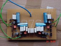
It is easy to build up the aleph3 on a standard board, like this
leave the inductor out, the commercial Alephs dont use it either.
I built mine without inductor, too, and theres no hum. Only when getting about two inches in front of the loudspeaker with your ears you can hear some.
You can also save space without it.
It is easy to build up the aleph3 on a standard board, like this
Attachments
Sweet, both questions answered
What about thermistors and inrush current suppressors? Do I need both of those?
As well, can someone post links (or part numbers) for either mouser or digikey for suitable ones?
Thanks again
(just trying to get an idea of how much it'll really cost in the end. gotta plan this right if i wanna do it so that i dont' run out of money)
Digikey part # KC006L-ND Inrush Current Limiter (thermistor)
Nice to have, makes things a bit easier on your PSU. You loose
maybe a volt or so off your rails with it. This part is also seen in
the BZLS article: Earth ground from the AC cord is attached to the chassis for
safety, and is connected to the circuit ground through a power thermistor
(bright idea from Frank DeLuca). This gives some resistive isolation for
prevention of ground loops but goes to small values of resistance in
case of catastrophic connection to the live AC line.
(even if you don't build the ZEN projects, you learn lots of neat stuff reading them!)
m.
Awesome, all my questions are getting answered
Thank you.
But I've more ..
The 0.47R resistors, is 3watts ok?
Is a 400VA with 22V on secondaries transformer ok? Or will the rail voltage be too high?
Also, I'll be using 6 33,000uF caps, so that should be enough.
I'm sure i'll have more q's by the end of the day
Thanks again, and I'll make sure to read the zen articles as soon as I have time (i read a couple, but wasn't able to concentrate on them fully, i'll re-read!)
The temperature rise should be no more than 25C (I'm using a slightly scaled down version of heatsinks i was going to use for an Aleph 5).
The reason I'm using a 400VA transformer is because that is the one I have on hand. Sadly, purchasing another transformer will cost me $120+ after shipping and tax
So, I chose to make use of what I have around
The reason I'm using a 400VA transformer is because that is the one I have on hand. Sadly, purchasing another transformer will cost me $120+ after shipping and tax
So, I chose to make use of what I have around
some more questions on the horizon
actually more of a request .. i've been searching for the whole day, and i've been trying to play around with some stuff .. no luck
i need a pcb drawing (component overlay w/ the values on each component + the tracks) .. that's to make it easier for me to visualize how to wire it on the breadboard when i do ..
i'd like to make a drawing first as to how i'm going to lay everything out on the breadboard .. makes my life easier, plus gives me something to do until i get money to buy the stuff
elizard said:some more questions on the horizon
actually more of a request .. i've been searching for the whole day, and i've been trying to play around with some stuff .. no luck
i need a pcb drawing (component overlay w/ the values on each component + the tracks) .. that's to make it easier for me to visualize how to wire it on the breadboard when i do ..
i'd like to make a drawing first as to how i'm going to lay everything out on the breadboard .. makes my life easier, plus gives me something to do until i get money to buy the stuff
Here's how I did mine (the component IDs are from the Aleph 30 manual):
http://www.diyaudio.com/forums/showthread.php?postid=260893#post260893
Allright, still waiting if anyone else has a layout, but in the meantime i'm making a BOM and the order w/ mouser.
They don't have a 390R vishay/dale resistor from the same series as all the other i'm getting (71-RN60D-F-...). They've a 392, would that be ok, or would that mess things up?
Thanks.
edit: and it seems that there's no 47K either
They don't have a 390R vishay/dale resistor from the same series as all the other i'm getting (71-RN60D-F-...). They've a 392, would that be ok, or would that mess things up?
Thanks.
edit: and it seems that there's no 47K either
Got another one concerning the power supply.
I'm going to use one transformer for the whole thing, and 2 bridges (1 for +, 1 for - rail)
Should I use 2 capacitors for the left channel, 2 for right, or 4 for both (capacitors not separate for the 2 channels)
Btw, the capacitors are 33,000uF.
I'm going to use one transformer for the whole thing, and 2 bridges (1 for +, 1 for - rail)
Should I use 2 capacitors for the left channel, 2 for right, or 4 for both (capacitors not separate for the 2 channels)
Btw, the capacitors are 33,000uF.
Elizard, I´m also in the process of building an Aleph3.
I´ll separate the caps for each channel and so having a kind of pseudo-mono approach. Still not sure if I should use one bridge for each rail which would mean to use 4 bridges, just like your first suggestion.
I´d go with 2 caps for each channel.
Don´t think it can worsen anything except you have 2 more bridges and a little more wiring which has to be carefully lead.
Being at it : Are the two grounds from the "separated" channels then preferably connected at the speaker outs (like in ZenV4 for example) or near the caps at starground?
Cheers
Jens
joensd said:Elizard, I´m also in the process of building an Aleph3.
I´ll separate the caps for each channel and so having a kind of pseudo-mono approach. Still not sure if I should use one bridge for each rail which would mean to use 4 bridges, just like your first suggestion.
I´d go with 2 caps for each channel.
Don´t think it can worsen anything except you have 2 more bridges and a little more wiring which has to be carefully lead.
Being at it : Are the two grounds from the "separated" channels then preferably connected at the speaker outs (like in ZenV4 for example) or near the caps at starground?
Cheers
Jens
What are you going to use for PCB? Are you going to order separate PCB's, or fabricate your own? Also, do you have a layout in mind (I've been trying to make my own, but being my first pcb its a little tedious and i'm not making that much progress).
I'm thinking of going 2 caps/channel, separate for the two channels, and then 2 bridges/channel. If I'm not mistaken, the original Aleph 3 used 8x22,000 common to both channels, but the Aleph 30 used 8x10,000 for EACH channel (separate).
Maybe it'd be a good idea if I used 2x33,000uF + 2x10,000uF for each channel?
I also think the grounds are separate in A30, but the same in A3 .. not 100% sure on this one however.
check out this thread for inspiration!
http://www.diyaudio.com/forums/showthread.php?s=&threadid=20573
http://www.diyaudio.com/forums/showthread.php?s=&threadid=20573
what i'd actually love to see (and i'm sure there's a fat chance of this, but ..) is the other side of kristijan's a3 pcb, or the component side w/ the component values marked on there, OR the component #s marked on his schematics .. but of course, thats his work .. maybe if he's reading, he'll be able to point me in the right direction (or someone else of course)
(or someone else of course)(sometimes i feel that i'm talking to myself .. lol)
anyway ..
i ran across a page for an aleph 5 using briangt's layout
http://www.prism.gatech.edu/~gte619j/alephpcb/
now .. on the page it shows partially how to use it with an aleph 3 .. just change a few resistors, eliminate a cap, etc ..
well, i tried working out a parts list for brian's board, since i can't find one .. and i can't find values for the following resistors (or i'm unsure of the values of them anyway):
R2, R3, R4, R5, R9, and R10
as far as capacitors go, i know i'm supposed to leave out C7, i just want to make sure i don't have to replace it with a jumper ..
Is C6 the 1nF capacitor from the original aleph 3 schematic?
What of C8? What's C8's value, and what is it for?
As well, I will not be using balanced input, just a regular unbalanced input. How does that change the layout? Do I just simply leave out R2 and R3?
As I said, there's LOTS of questions
Thanks
- Status
- This old topic is closed. If you want to reopen this topic, contact a moderator using the "Report Post" button.
- Home
- Amplifiers
- Pass Labs
- Aleph 3 questions