ungie said:I'd love to learn some details of the SuperIt mods you have performed. I have a mint unit here that blew the main power supply cap some years ago.
Well discussion on modifying a NYAL Super It doesn't really belong in the Pass forum. Here are some brief comments. Further discussion should move elsewhere.
Failure of the power supply caps is a classic failure mode in the Super It. It used Photoflash capacitors which tend to die early. Replace them with the biggest Panasonic TSHA capacitor that fits the board pin spacing. You should also replace the diodes with Hexfreds or other good quality low noise diode. I'd upgrade the regulator op amp to an OPA2604 and put a 0.1uf polypro cap across the filaments right at the tube sockets. This is a good start to resurrecting the super it. You can also upgrade coupling caps and riaa caps to good effect. Then if you want to go truly overboard you can replace resistors in the riaa and the cartridge loading circuit.
---Gary
Re: Re: Bootstrapped cascode
Gary,
sorry for the delay on my reply.
I will quote something and answers are inserted below
YEs, even Aura Teflon would be very nice, even a better choice than Relcap.
the only problem is to find a 2700pF available.
I can easily find the 2700pF Auricap Cap.
I would be interested on Aura Teflon, if anybody can help me out to find the 2700pF i would love to use these caps.
Of course, PartsConn gives a very good price on these caps.
Expense is also a matter of concern.
For the led: I know you need to re-adjust the current source mirror, of course, to properly set the current on the diff input and on the output stage.
The point is that i think that a monolithic IC would be better than a LED and the expense is not that much (of course 2 good IC can be like 100 LEDS...so there you are") )
)
I don't catch the fact the 2 pins voltage reference subject.
Every voltage reference would perfectly fit there.
I you just need an input voltage to feed it with and you can use the output to properly bias the cascode.
Am I saying something wrong?
I disagree with the quality of the LM336.
I think that a better choices might be achieved, but i do agree yet, it is a decent voltage reference.
If you look at the curve you have just posted you will notice that non-linearityes decrease by increasing VDS and a good spot would be something around 8-10V.
I have also read various experiences on cascoding and good results, soundwise speaking are always achieved with a VDS over 7V.
Just my two cents.
Anyways, thank you very much Gary for your useful post.
I think this is a very additive subject for who wants to build a ONO.
Just one stupid question on cartridge load's matching:
I am going to use a Denon DL 103.
It is a 0.33mV output pick up with a suggested load of around 100ohm.
The question is:
when a MC pick up is used do I need to set the capacitance at the input of the MM stage?
If i decide to only use the MC, can i get rid of the input capacitance selection and only use the resistance selection at the MC input's stage?
Gary,
sorry for the delay on my reply.
I will quote something and answers are inserted below
GaryB said:
I've never listened to naked Vishay resistors but I suspect they will be fine. Regarding the RIAA capacitors, I don't think that Auricaps come in the right values. I was looking at the Partsconnexion website and see that Relcap has Teflon 0.01uf and 0.033uf 200v caps that would be excellent. They are expensive but I would recommend that expense. If budget is limited then I'd spend money on the teflon caps before the expensive resistors.
For the 2x220uf caps, I agree with Analog-sa that the Black Gate 220uf 6.3v NX capacitor is a much better choice.
The voltage of the LED is much less than 5v, so you will need to adjust the values of the resistors in the emitters of the current mirror transistors to get the right currents. I don't think this is worth the trouble since LEDs are already low noise.
In the bootstrap cascode, you can not use the AD586. You need to use a two terminal device such as a zener diode and the LM336 that I used is a very good low noise zener. Don't change this.
Yes, that is a typing error. It should have been R67.
Regards,
---Gary
YEs, even Aura Teflon would be very nice, even a better choice than Relcap.
the only problem is to find a 2700pF available.
I can easily find the 2700pF Auricap Cap.
I would be interested on Aura Teflon, if anybody can help me out to find the 2700pF i would love to use these caps.
Of course, PartsConn gives a very good price on these caps.
Expense is also a matter of concern.
For the led: I know you need to re-adjust the current source mirror, of course, to properly set the current on the diff input and on the output stage.
The point is that i think that a monolithic IC would be better than a LED and the expense is not that much (of course 2 good IC can be like 100 LEDS...so there you are
)I don't catch the fact the 2 pins voltage reference subject.
Every voltage reference would perfectly fit there.
I you just need an input voltage to feed it with and you can use the output to properly bias the cascode.
Am I saying something wrong?
I disagree with the quality of the LM336.
I think that a better choices might be achieved, but i do agree yet, it is a decent voltage reference.
GaryB said:
Martin,
Thanks for the comments.
I respectfully disagree. If the current is changing between the two halves of the differential pair then the voltage of the common sources has to change. It changes less than the signal level since currents in jfets have a square law dependence on the voltage change, but it does change. We can argue whether or not this effect is significant or not but my experience has been positive with the use of the bootstrap cascode configuration so my experience is that this effect is important.
I never experimented with this. The datasheet of the 2SK389 shows that even 5v is plenty to put the transistors into the saturation region, which is the goal. But they can handle higher voltage and it would not hurt. I suspect the effect won't be significant.
---Gary
If you look at the curve you have just posted you will notice that non-linearityes decrease by increasing VDS and a good spot would be something around 8-10V.
I have also read various experiences on cascoding and good results, soundwise speaking are always achieved with a VDS over 7V.
Just my two cents.
Anyways, thank you very much Gary for your useful post.
I think this is a very additive subject for who wants to build a ONO.
Just one stupid question on cartridge load's matching:
I am going to use a Denon DL 103.
It is a 0.33mV output pick up with a suggested load of around 100ohm.
The question is:
when a MC pick up is used do I need to set the capacitance at the input of the MM stage?
If i decide to only use the MC, can i get rid of the input capacitance selection and only use the resistance selection at the MC input's stage?
Gary,
i have just noticed on the picture of you ono posted in this section, that you are using Zen Film caps.
It it right?
Are you using them as coupling cap for the MC stage?
I have been using them on my other implementations and i have been really pleased with the sound.
Did you have a chance to compare them with other film caps and formed an opinion?
I would have loved to use them on the equalization network but they don't come in the right values so.
Re: Re: Re: Bootstrapped cascode
100ohm is ok and you may also experiment. I use 470 but it's not very critical. MC carts are not particularly sensitive to loading capacitance anyway but loading the output of the MC step-up is plain silly.
Stefanoo said:a suggested load of around 100ohm.
The question is:
when a MC pick up is used do I need to set the capacitance at the input of the MM stage?
100ohm is ok and you may also experiment. I use 470 but it's not very critical. MC carts are not particularly sensitive to loading capacitance anyway but loading the output of the MC step-up is plain silly.
Right, 100ohm or higher (even better) is the suggested load for the DL103.
Got it: capacitance load in not a matter of big concern for a MC pick-up.
This phono linked below (which is the one i have been owning for quite a bit) uses a 1.1nF cap at the input of the MC stage.
http://www.trichordresearch.com/dino.html
(hit technical specs section.)
The ono, instead, has 100pF i guess to prevent RF to get through, but:
Have you ever played with the value of this cap?
Last thing and I actually didn't find this information around on other 3ds (ether i missed it or this thing makes no sense).
Anyways, with regard to the output stage of the MM section:
should the 2 push-pull class A biased output devices 610/9610 (Q18/7) be symmetric i.e. complementary matched to achieve optimal performance?
Re: Re: Re: Bootstrapped cascode
Stefano,
The Relcap TFE (polystyrene film and foil) caps are very nice and will provide the right values to finish the RIAA network. I still recommend the Teflon caps where you can find them but you can use the Relcaps to finish the network in case you don't find all the teflon caps and you will still have a very good result.
----Gary
Stefanoo said:YEs, even Aura Teflon would be very nice, even a better choice than Relcap.
the only problem is to find a 2700pF available.
Stefano,
The Relcap TFE (polystyrene film and foil) caps are very nice and will provide the right values to finish the RIAA network. I still recommend the Teflon caps where you can find them but you can use the Relcaps to finish the network in case you don't find all the teflon caps and you will still have a very good result.
----Gary
Re: Re: Re: Bootstrapped cascode
A two terminal voltage reference just has an anode and a cathode.
A three terminal device has Vin, Vout, and Ground. This type of device doesn't work for a bootstrap cascode since one wants the Vout / Ground terminals to float up and down with the signal. The Vin terminal makes it hard to move the other 2 terminals with the signal. As I said earlier, you must use a low noise zener for the bootstrap cascode. A low noise voltage reference will note work.
---Gary
Stefanoo said:I don't catch the fact the 2 pins voltage reference subject.
Every voltage reference would perfectly fit there.
I you just need an input voltage to feed it with and you can use the output to properly bias the cascode.
Am I saying something wrong?
I disagree with the quality of the LM336.
I think that a better choices might be achieved, but i do agree yet, it is a decent voltage reference.
A two terminal voltage reference just has an anode and a cathode.
A three terminal device has Vin, Vout, and Ground. This type of device doesn't work for a bootstrap cascode since one wants the Vout / Ground terminals to float up and down with the signal. The Vin terminal makes it hard to move the other 2 terminals with the signal. As I said earlier, you must use a low noise zener for the bootstrap cascode. A low noise voltage reference will note work.
---Gary
Re: Re: Re: Bootstrapped cascode
These days I strongly prefer step up transformers over an active MC stage. I recommend you just get rid of the MC stage in the ONO and only use the MM stage. Then you can use a transformer to step up the signal from the DL103. It will sound very good and avoid all the issues with the quality of the ONO MC stage.
---Gary
Stefanoo said:I am going to use a Denon DL 103.
It is a 0.33mV output pick up with a suggested load of around 100ohm.
The question is:
when a MC pick up is used do I need to set the capacitance at the input of the MM stage?
If i decide to only use the MC, can i get rid of the input capacitance selection and only use the resistance selection at the MC input's stage?
These days I strongly prefer step up transformers over an active MC stage. I recommend you just get rid of the MC stage in the ONO and only use the MM stage. Then you can use a transformer to step up the signal from the DL103. It will sound very good and avoid all the issues with the quality of the ONO MC stage.
---Gary
Re: Re: Re: Re: Bootstrapped cascode
This is how i use the Ono at present. From all the cheap transformers i've tried i only liked the Tribute and the amorphous Lundahl. Transformers are another contentious mine field - lots of opportunity to make the wrong choice. I find active step-ups safer and cheaper and in some aural aspects - better.
GaryB said:
I recommend you just get rid of the MC stage in the ONO and only use the MM stage.
This is how i use the Ono at present. From all the cheap transformers i've tried i only liked the Tribute and the amorphous Lundahl. Transformers are another contentious mine field - lots of opportunity to make the wrong choice. I find active step-ups safer and cheaper and in some aural aspects - better.
Hi Gary,
lets start from the caps.
TFE Relcap are not as good as the Auricaps and that's for sure.
The Teflon Caps might be better.
Unfortunately they don't come in all the needed values (2700pF) and i would rather use all auricaps rather than using 2 better caps and a cheap one.
The sound will be almost determined by the worse cap you have on your network.
If i would find all Teflon caps that this would be my choice.
For the bootstrap, i understand what you are saying about the variable ground.
The voltage reference would have to refer to the voltage variable source of the differential.
But what if the ground would be taken on the source (for both Vin and Vout?) ...i don't know if this would work.
Anyways the LM336 is a nice low noise zener it just comes in 2.5V or 5V output.
how about LM4040 by texas.
It's a 40ppm low noise zener.
About the MC step-up:
by getting rid of the inverting buffer stage and thus of the 2 coupling caps and recuperating the absolute phase at the cartridge's clip, i think that this is a nice and simple MC stage which quality depends upon the quality of the parts chosen so:
coupling cap, resistors, matching of the n-jfet, resistors, power supply topology.
If the above parameters are kept enough high then a good result will be achieved.
Just my two cents.
In the next weeks i will be making my interpretation of the ONO and post all the impressions, details and pics to share my experience with you guys.
Stefanoo said:TFE Relcap are not as good as the Auricaps and that's for sure.
Stefano,
This is a meaningless statement since Auricap doesn't make small capacitors in the range needed for the RIAA. I have said that Teflon caps are my recommendation for the RIAA network but what will you do if you can't find the exact values listed in the ONO circuit diagram? You can redesign the RIAA network to use the Teflon caps that you do have. That's not too hard. Or you can use mostly Teflon caps and add other caps as needed.
Stefanoo said:Anyways the LM336 is a nice low noise zener it just comes in 2.5V or 5V output. how about LM4040 by texas. It's a 40ppm low noise zener.
Look at the datasheets. The LM4040 is higher noise than the LM336. It's primary advantage is very low current to start zener action which isn't critical for this application.
Stefanoo said:
About the MC step-up:
. . . i think that this is a nice and simple MC stage which quality depends upon the quality of the parts chosen so:
coupling cap, resistors, matching of the n-jfet, resistors, power supply topology.
If the above parameters are kept enough high then a good result will be achieved.
Definitely try it and see how you like it. My experience has shown that step up transformers sound better in my system. You need good transformers and it's important to load them properly at both the primary and secondary. I've found that most transformers sound better with a higher resistance on the secondary (100K or higher) and most of the cartridge load on the primary.
---Gary
Gary,
what i was trying to say is that i can supply all the values needed for the RIAA network with auricap (i found the 2700pF)
I am getting interested in re-designing the RIAA network with other values (Teflon Caps).
I will see whether Relcap or Vcap might be the right choice.
The only thing i don't like is having to use 2 different brands of film caps.
If i use Teflon caps for the network then I can't spend $100 for a 10uF coupling cap.
Even the Dynamicap are very nice premium caps to use. what do you think?
Is there anybody that had experiences with Teflon Cap: Vcap, relcap or other?
Just one thought on current mirror and current source/sink:
i have carefully read the experiments of Jung on current source and he examines different topologies.
The topology using the IC (LM336) to bias and cascoding the device seems to offer a far better performance than the simple device biased by a single LED.
Even the current diode J507 with cascode seems to achieve a very good result.
The point is that i can't source this j507 anywhere (i will make more researches).
The question is:
why would a current mirror topology be chosen with one side as a tail of the diff pair and the other as bias for the driving stage of the push pull output stage over two separate current sinks?
Is there any advantage on doing this or not?
With regard to the LM336, you are right is lower noise than the one i have pointed out before
Unfortunately it only comes on 2.5 or 5V and I still don't like the idea of a bootstrap cascode with a Vds under 8-10V.
I would like to find a good low noise zener at 10V (i don't ether like the idea of having two in series).
Any suggestion?
Hi everybody,
i am just done with the new RIAA network.
I like it a lot and i can't wait to put everything together and try it out
....i know it will take awhile....but that's ok.
I want to share my results with you guys so feel free to comment.
Just a short description:
Got rid of the 2 X 220uF electrolytic cap on the RIAA network as i have always thought it was pointless to have good Teflon cap and Electrolytics messing up the fine quality of the other film caps.
Anyways: the nice thing is that (i am just going to use MC so no MM inputs) with the same amount of coupling cap from the MC to the MM stage the bottom end response is much more extended.\
By increasing the resistor R20 up to 200Kohm (can this high value eventually create issue with stray field pick up?) with a 2.2uF coupling cap the low freq response is down to 1.2Hz or so.
This is very nice: with the same price of a good 10uF or higher film cap, I can buy an excellent lower value Mundorf Silver/oil or silver Gold Cap.
Since the MC stage, once the buffer stage is removed, is global feedback-less , I feel that quality of the stage strongly depends upon coupling caps and surrounding parts.
All values chosen for the RIAA are available on the V-CAP TFTF Range.
Resistor are Naked Vishay S102
All the results posted are obtained using a 2.2uF 200Kohm high pass filter from the MC to the MM.
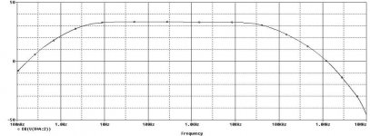
First pic is the original network (0.1Hz 10MHz)
Feel free to comment.
i am just done with the new RIAA network.
I like it a lot and i can't wait to put everything together and try it out
....i know it will take awhile....but that's ok.
I want to share my results with you guys so feel free to comment.
Just a short description:
Got rid of the 2 X 220uF electrolytic cap on the RIAA network as i have always thought it was pointless to have good Teflon cap and Electrolytics messing up the fine quality of the other film caps.
Anyways: the nice thing is that (i am just going to use MC so no MM inputs) with the same amount of coupling cap from the MC to the MM stage the bottom end response is much more extended.\
By increasing the resistor R20 up to 200Kohm (can this high value eventually create issue with stray field pick up?) with a 2.2uF coupling cap the low freq response is down to 1.2Hz or so.
This is very nice: with the same price of a good 10uF or higher film cap, I can buy an excellent lower value Mundorf Silver/oil or silver Gold Cap.
Since the MC stage, once the buffer stage is removed, is global feedback-less , I feel that quality of the stage strongly depends upon coupling caps and surrounding parts.
All values chosen for the RIAA are available on the V-CAP TFTF Range.
Resistor are Naked Vishay S102
All the results posted are obtained using a 2.2uF 200Kohm high pass filter from the MC to the MM.
First pic is the original network (0.1Hz 10MHz)
Feel free to comment.
Attachments
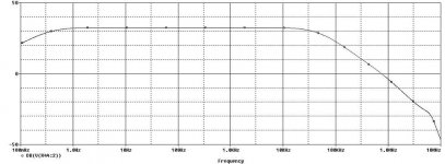
Now, new RIAA 0.1Hz -10MHz
in this configuration i can see a little peak at 8MHz or so which i have no clue if can cause any HF unstability issues or not.
The top freq resp can be smoothed a little more by changing the cut frequency of the HF filter.
A 180KHz freq cut was chosen to take full advantage of the top end response of the amplifier awhile on the original i think it was set at around 150KHz or so.
Attachments
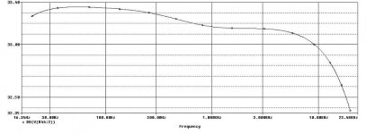
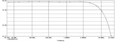
last pic is the close shoot at the new network in the 20Hz-20KHz range.
This last pic if compared with the original shows a better RIAA equalization.
The difference is small but yet, still nice to have slight improvement over the already good RIAA eq of the original.
the nicest thing of this network is that allows a lower coupling cap value and yet achieving a lower low freq cut and second allows to get rid of the 2 annoying 220uF Electrolytic cap.
any comment is appreciated.
Attachments
Gary,
I will try to explain it better.
My modifications involved the RIAA network.
I have changed the configuration of the RIAA and with the new one i got a lower cut off frequency and a little better RIAA equalization.
The lower cut off freq allows me to choose a lower value for the coupling capacitor (with 2.2uF the cut off freq is under 1Hz).
I have a question:
can the the former resistor of th DC blocking filter this be scaled up as much as i want and use a lower DC blocking cap?
Is there any drawback by choosing lets say 1uf 200Kohm rather than 2.2uf 90Kohm?
The higher impedance should come handy since the inverting/buffer stage on the MC has been taken off, right?
Anyways, going back to the pictures i have posted:
they referred to the original RIAA network (the ONO) and the modified one,respectively.
I have posted for each one the frequency response on the 0.1Hz-10MHz range and on the 20Hz-20KHz range to see in more detail the RIAA response on the audio spectrum.
the first two are referring to the ono and the last two to the modified network.
if something is not clear yet, please let me know and i will try to clear it up
Stefano,
A few comments. Rather than give you answers to your questions, I am going to try to teach you how to get the answers on your own.
1)How do you set the resistor at the input of the MM section of the ONO?
The original value is 47kohms, which is standard loading for a MM stage. You can increase this as long as the gate current from the 2SK389 has a good path to ground and doesn't lead to large voltages. That means that Ig x Rin should be very small. Look at the 2SK389 datasheet and estimate the gate current at the operating conditions. You should find out that 200kohms for the input resistor is fine.
2)Can you get rid of the 220uf DC blocking capacitors in the MM section?
Those caps are needed if you can not guarantee that the output of the stage will have 0v on it. The design of the ONO uses a DC blocking output cap which means that those 200uf caps are also needed. Change the circuit so that there is no DC on the output and then you can get rid of those 220uf caps.
3)Can you arbitrarily change the resistor in series with the 220uf caps?
This caps sets the gain of the MM stage along with the other parts of the RIAA network. Making it a bigger value will decrease the gain, which probably isn't a good idea.
4)Other comments.
The response of the MM stage should not be flat. The RIAA network means that it should have gain that drops with frequency. Your curves showing flat frequency response confuse me because they don't show the proper RIAA filter response.
---Gary
Gary,
wait a second, we are out of synchronism
It's time to line up
that's ok, it's probably my fault!
Let me thank you for the first point.
It was a good one.
I didn't know that. i will try to think over what you have said, check the datasheet and maybe get back to you if i have doubts.
Point (2):
are you referring to the output coupling cap (10uF) or at the MC output coupling cap?
The output coupling cap can be eliminated by just adjusting the dc offset at the output through the resistor R4, but i thought that it was clear since the beginning and that is what you have done as well, right?
For the other coupling cap, i mean to say, the coupling cap from the MC to the MM stage: It can't be eliminated for this topology chosen, of course.
Nevertheless that is what i was referring to, when i said I would like to lower it as much as possible and thus increasing the 47kohm resistor at the input of the MM up to 200Kohm (since no MM cart will be connected but ONLY MC), low cut off frequency can be managed to be under 1Hz.
That would allow me to use a good 1uF Aura Teflon Cap (i know all exotic parts )
Point (3):
i think that you are referring to C1, C41 on the RIAA network when you talk about setting the gain, right (since as far as i am concerned that resistor control the gain of the MM stage)?
If not, please explain this better.
You are right: these caps CANNOT be eliminated on the actual RIAA network's configuration.
What I was saying though, was that RIAA network was re-designed. i didn't just take the 2 X 220uF off, of course .
On this configuration, there is NO need for such a high value cap and therefore ONLY Teflon V-CAP will be used.
Actually i have been keep playing around with values and RIAA accuracy is now around 0.1dB on 20-20KHz range: not baad!!!
The only problem is that, in order to make one value, i need to parallelize 2 Capacitors and if V-Cap will be used price for 2 units....is a wee bit high but that's ok, since the result obtained is really appealing.
point (4):
i didn't specify it, you are right, but i gave it for granted:
if you see a flat response on the wide 0.1Hz 10MHz range, you might wanna think that an inverse RIAA filter to evaluate the flatness of the response at the output is used
feel free to comment!
Best,
Stefano.
P.S. nobody replied at the question is matching of the complementary devices ot the output stage is needed for minimum distortion.
wait a second, we are out of synchronism
It's time to line up
that's ok, it's probably my fault!
Let me thank you for the first point.
It was a good one.
I didn't know that. i will try to think over what you have said, check the datasheet and maybe get back to you if i have doubts.
Point (2):
are you referring to the output coupling cap (10uF) or at the MC output coupling cap?
The output coupling cap can be eliminated by just adjusting the dc offset at the output through the resistor R4, but i thought that it was clear since the beginning and that is what you have done as well, right?
For the other coupling cap, i mean to say, the coupling cap from the MC to the MM stage: It can't be eliminated for this topology chosen, of course.
Nevertheless that is what i was referring to, when i said I would like to lower it as much as possible and thus increasing the 47kohm resistor at the input of the MM up to 200Kohm (since no MM cart will be connected but ONLY MC), low cut off frequency can be managed to be under 1Hz.
That would allow me to use a good 1uF Aura Teflon Cap (i know all exotic parts
) Point (3):
i think that you are referring to C1, C41 on the RIAA network when you talk about setting the gain, right (since as far as i am concerned that resistor control the gain of the MM stage)?
If not, please explain this better.
You are right: these caps CANNOT be eliminated on the actual RIAA network's configuration.
What I was saying though, was that RIAA network was re-designed. i didn't just take the 2 X 220uF off, of course
.On this configuration, there is NO need for such a high value cap and therefore ONLY Teflon V-CAP will be used.
Actually i have been keep playing around with values and RIAA accuracy is now around 0.1dB on 20-20KHz range: not baad!!!
The only problem is that, in order to make one value, i need to parallelize 2 Capacitors and if V-Cap will be used price for 2 units....is a wee bit high
but that's ok, since the result obtained is really appealing.point (4):
i didn't specify it, you are right, but i gave it for granted:
if you see a flat response on the wide 0.1Hz 10MHz range, you might wanna think that an inverse RIAA filter to evaluate the flatness of the response at the output is used
feel free to comment!
Best,
Stefano.
P.S. nobody replied at the question is matching of the complementary devices ot the output stage is needed for minimum distortion.
- Status
- This old topic is closed. If you want to reopen this topic, contact a moderator using the "Report Post" button.
- Home
- Amplifiers
- Pass Labs
- Aleph ONO working - belated thanks to pquadrat