Hi all,
I finally got my Aleph ONO phono stage working. I used the pcb boards that pquadrat laid out and offered up to the DIY community. More details on the boards are found here:
http://www.diyaudio.com/forums/showthread.php?threadid=10326
I did change the design slightly and didn't build in all the functionality that is possible. I didn't bother with the relays since I intend to leave it on all the time. I also didn't need balanced operation, so I eliminated those parts. I also got rid of the output coupling cap per the modification suggested by Peter Daniel.
Other than that I built it as designed. After a bit of listening I decided that I didn't quite like the MC stage and went to the simpler Pearl type 1st stage. This means taking the output directly from R40 and bypassing the last 2SK170 and the electrolytic coupling caps. This cleaned up the mids but slightly hurt the highs. Thinking that this might be related to the moderately high output impedance of the stripped down MC stage, I tried converting the input of the MM stage from cascode to bootstrap cascode.
To do this I removed R17 (10k to ground) and inserted a low noise zener (5v LM336, bypassed with 0.1uf pp cap) from the bases of Q1,2 to the sources of Q5. To get the biases right, I changed R3 to 29Kohm and R7 to 332ohms. This puts about 0.9ma through the zener and keeps the bias of the input transistors unchanged. This change worked very well and restored the nice highs of the original circuit and left the midrange clarity of the simplified MC stage and its what I'm listening to now.
Oh one last hint - I originally used a silver mica cap for C3, which is critical for the high frequency stabilization of the circuit. This didn't seem to cause a problem with the original circuit but with the change to bootstrap cascode this was problematic. Changing to a ceramic returned the circuit to its original well behaved state, suggesting that silver micas don't do too well in the Mhz range.
---Gary
Attachments
Schematic
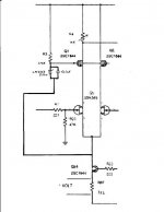
There hasn't been much response to this, but for completeness I thought I'd include a schematic to make the details of the MM input stage modification clearer.
---Gary
GaryB said:I tried converting the input of the MM stage from cascode to bootstrap cascode.
To do this I removed R17 (10k to ground) and inserted a low noise zener (5v LM336, bypassed with 0.1uf pp cap) from the bases of Q1,2 to the sources of Q5. To get the biases right, I changed R3 to 29Kohm and R7 to 332ohms. This puts about 0.9ma through the zener and keeps the bias of the input transistors unchanged.
---Gary
There hasn't been much response to this, but for completeness I thought I'd include a schematic to make the details of the MM input stage modification clearer.
---Gary
Attachments
What do you mean analog?
I thought of posting this thing in accordance to what we were saying on the other 3d.
He did the same thing but interesting he found that changing the cascode configuration changed the sound.
I personally don't see how a bootstrap cascode might fix a impedance problem though, if there was an impedance problem...but it is certainly my lack of knowledge so I hope Gary will post again.
Sadly that an interesting subject with this didn't catch any attention.
Stefanoo said:this post is old...but very interesting.
Are you still using your ONO?
Did you make any other change to it?
Stefano,
Thanks for your interest. It's been almost 5 years since I built the ONO so it's surprising that someone found this old message. I'll try to answer your questions as best I can.
First, I still have the ONO and it works fine and I use it from time to time. My main phono stage is a highly modified NYAL Super It tube phone stage. It uses an FET/tube input stage, passive RIAA, followed by another FET/tube gain stage, and a MOSFET source follower output stage. It sounds slightly better than the ONO but the difference is small.
The only other tweaks I made to the ONO were to upgrade the RIAA network parts. I changed the resistors to TaN film SMD resistors from IRC. You can see them here:
http://www.mouser.com/catalog/636/621.pdf
I also managed to find teflon film caps and use of these caps made a big difference in sound quality. I don't have a good source to recommend. I found the 0.01uf cap from someone here in diyaudio and the other caps on ebay.
analog_sa said:Interesting indeed. Sadly, the technical part does not make a lot of sense, at least to me.
Stefanoo said:What do you mean analog?
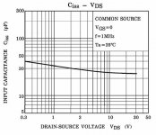
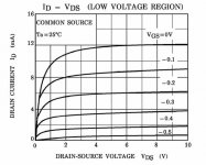
I'm also not sure I understand the comment from Analog-sa. He probably thinks that the input impedance of the MM stage is set by the 47k resistor at the input to the 2SK389 and the output impedance of the MC stage doesn't matter. Perhaps he's right but I don't think so. If you look at the datasheet for the 2SK289, you'll see that the input capacitance changes as Vds changes. I've attached this figure below. The bootstrap cascode configuration keeps Vds constant and eliminates this tendency for Ci to change with signal. I think this effect is more noticeable when you drive this with a high output impedance.
Even if the technical explanation is flawed, the sound quality is definitely improved by this change. It's not too hard so why not try it out.
---Gary
Attachments
GaryB said:
He probably thinks that the input impedance of the MM stage is set by the 47k resistor at the input to the 2SK389 and the output impedance of the MC stage doesn't matter.
Hi Gary
Your suspicion is correct. You may be right with your explanation; it's just impossible to prove you are not compensating for the different distorion spectrum after the removal of the NFB stage. It would be interesting to listen to a MM cartridge with and without bootstrapping.
thank you Gary.
This is such a good technical comment.
Thanks a lot.
I will try this out for sure.
With regard to resistors i am planning on using Naked Vishay S102 that are premium resistors.
For cap, still premium one, with Auricap Film Caps.
Electrolytic will be Black gates STD for the smoothing caps and F for the RIAA 2 X 220uF (which i will replace with just one 470uF).
I will use the monolithic for the cascoding of the @SK381 instead of the 2 transistors and same thing for the current mirror.
I am planning on using the 5V reference voltage AD586 (it's 2ppm with an extra low residual noise) on both current mirror and bootstrap.
- if you want to comment this last modification i don't know if you tried to replace the led with a good voltage reference-
One question:
you said you had to change the bias resistor R3 (ok) and R7 (? did you change this one? did you mean to say R67? this sets the bias on the differential amp along with the voltage reference. which by the way what does R7 do? i find it on the main diagram for active RIAA so i guess is part of the equalization network, right?)
Thank you Gary for your relevant post.
I have never tried Auricap actually.
Up till now i was content with Zen caps.
Unfortunately they don't have values suitable for RIAA applications.
Nevertheless from the multiple researches i have done so fare Auricaps are the best, reasonable priced speaking, film caps on the market.
They are widely used on all kinds of modifications/tweaks and so on.
They are not as good as Dynamicap or others, of course.
I would use dynamicap actually, but i can't find any source for the 2700pF RIIA cap and i don't like to use 2 brands for the RIAA network.
If you wish you can tell me what is the best film cap accordingly to your experience that canbe found on the value required from the network in exame.
Speaking of BG: yes, I am sure they are good, but i don't mind taking more space on the board Vs having eletrolytic, although good ones, on the RIAA network or on signal path in general.
")
Bootstrapped cascode
Excuse my ignorance, and maybe I do not understand differential pairs well enough, but I do not see that you are really bootstrapping the common base transistors. You are referencing the cascode to the connection of the common sources with the current source. However, this point should have a more or less fixed voltage - in other words the effect would be the same as referencing the cascode to ground. If one side of the K389 is conducting less the CCS is just forcing more current to the other half, but their voltage should remain fixed.
Secondly, the signal voltages are so small that the capacitance of the K389 should not really change, besides it should be too low to make any differences in the load. So I do not "buy" this explanation either.
My last comment before I shut up: I believe the 5 Volt reference is setting the drain to source voltage too low. As a minimum I would try 2 references in series to get 10 Volts, that is if you must use them in the first place.
Stefanoo said:With regard to resistors i am planning on using Naked Vishay S102 that are premium resistors. For cap, still premium one, with Auricap Film Caps. Electrolytic will be Black gates STD for the smoothing caps and F for the RIAA 2 X 220uF (which i will replace with just one 470uF).
I've never listened to naked Vishay resistors but I suspect they will be fine. Regarding the RIAA capacitors, I don't think that Auricaps come in the right values. I was looking at the Partsconnexion website and see that Relcap has Teflon 0.01uf and 0.033uf 200v caps that would be excellent. They are expensive but I would recommend that expense. If budget is limited then I'd spend money on the teflon caps before the expensive resistors.
For the 2x220uf caps, I agree with Analog-sa that the Black Gate 220uf 6.3v NX capacitor is a much better choice.
I am planning on using the 5V reference voltage AD586 (it's 2ppm with an extra low residual noise) on both current mirror and bootstrap.
- if you want to comment this last modification i don't know if you tried to replace the led with a good voltage reference-
The voltage of the LED is much less than 5v, so you will need to adjust the values of the resistors in the emitters of the current mirror transistors to get the right currents. I don't think this is worth the trouble since LEDs are already low noise.
In the bootstrap cascode, you can not use the AD586. You need to use a two terminal device such as a zener diode and the LM336 that I used is a very good low noise zener. Don't change this.
One question:
you said you had to change the bias resistor R3 (ok) and R7 (? did you change this one? did you mean to say R67?
Yes, that is a typing error. It should have been R67.
Regards,
---Gary
Re: Bootstrapped cascode
Martin,
Thanks for the comments.
I respectfully disagree. If the current is changing between the two halves of the differential pair then the voltage of the common sources has to change. It changes less than the signal level since currents in jfets have a square law dependence on the voltage change, but it does change. We can argue whether or not this effect is significant or not but my experience has been positive with the use of the bootstrap cascode configuration so my experience is that this effect is important.
I never experimented with this. The datasheet of the 2SK389 shows that even 5v is plenty to put the transistors into the saturation region, which is the goal. But they can handle higher voltage and it would not hurt. I suspect the effect won't be significant.
---Gary
MRupp said:. . . I do not see that you are really bootstrapping the common base transistors. You are referencing the cascode to the connection of the common sources with the current source. However, this point should have a more or less fixed voltage - in other words the effect would be the same as referencing the cascode to ground. If one side of the K389 is conducting less the CCS is just forcing more current to the other half, but their voltage should remain fixed.
Martin,
Thanks for the comments.
I respectfully disagree. If the current is changing between the two halves of the differential pair then the voltage of the common sources has to change. It changes less than the signal level since currents in jfets have a square law dependence on the voltage change, but it does change. We can argue whether or not this effect is significant or not but my experience has been positive with the use of the bootstrap cascode configuration so my experience is that this effect is important.
My last comment before I shut up: I believe the 5 Volt reference is setting the drain to source voltage too low. As a minimum I would try 2 references in series to get 10 Volts, that is if you must use them in the first place. [/B]
I never experimented with this. The datasheet of the 2SK389 shows that even 5v is plenty to put the transistors into the saturation region, which is the goal. But they can handle higher voltage and it would not hurt. I suspect the effect won't be significant.
---Gary
Attachments
photos
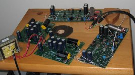
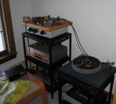
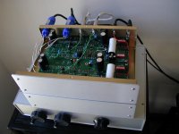
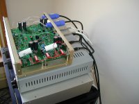
Here is a photo of my ONO in it's final configuration. Originally I stacked the power supply directly below the ONO as shown in the photo but this caused problems. Even with toroidal transformers, I got enough magnetic coupling between the units that there was an unacceptable hum. I found that the power supply needs to be at least 1 foot (30cm) away from the amplification circuits.
---Gary
Attachments
GaryB said:
My main phono stage is a highly modified NYAL Super It tube phone stage. It uses an FET/tube input stage, passive RIAA, followed by another FET/tube gain stage, and a MOSFET source follower output stage. It sounds slightly better than the ONO but the difference is small.
---Gary
Hi Gary,
I'd love to learn some details of the SuperIt mods you have performed.
I have a mint unit here that blew the main power supply cap some years ago.
I have been thinking of pulling it out of storage and making some upgrades.
Thanks!
If the current is changing between the two halves of the differential pair then the voltage of the common sources has to change.
Gary, you are off course right, the voltgage should change. As I said I did not understand this quite properly. Since this is the summing point of the input and the feedback signal it should somehow be the differential. I might try and sim this to better understand what the combined signal looks like.
- Status
- This old topic is closed. If you want to reopen this topic, contact a moderator using the "Report Post" button.
- Home
- Amplifiers
- Pass Labs
- Aleph ONO working - belated thanks to pquadrat