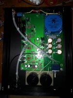
Yes, if I disconnect the cd player it is always noisy
check you headphone amplifier.Hum noise
Short the inputs with a dummy zero ohms plug fitted to both inputs.
Remove the headphone load and switch ON.
Measure the output DC offset and the Output Hum+Noise.
If the levels of both are low, then you should get down to the 199.9mV scales on you DMM and you should get readings of <5.0mVdc and <0.1mVac.
Test and report back.
Ground the body of the volume control.
Already done but nothing
check you headphone amplifier.
Short the inputs with a dummy zero ohms plug fitted to both inputs.
Remove the headphone load and switch ON.
Measure the output DC offset and the Output Hum+Noise.
If the levels of both are low, then you should get down to the 199.9mV scales on you DMM and you should get readings of <5.0mVdc and <0.1mVac.
Test and report back.
Here is a series of measurements
DC offset 0.6 mV
L out (potentiometer max) 7.4mV
R out (potentiometer max) 7.9mv
L out (poti min) 7.4mV
R out (poti min) 7.9 mV
L out (poti half a turn) 1.6 mV
R out (poti half a turn) 2mV .
What is AC volts and what is DC volts?Here is a series of measurements
DC offset 0.6 mV
L out (potentiometer max) 7.4mV
R out (potentiometer max) 7.9mv
L out (poti min) 7.4mV
R out (poti min) 7.9 mV
L out (poti half a turn) 1.6 mV
R out (poti half a turn) 2mV .
What is AC volts and what is DC volts?
The measures of the previous post are in DC
These instead in AC
L out 0.017V AC
R out 0.0018V AC
What is AC ripple across each power supply rail ie between positive and 0V and negative and 0V after the regulators?
0.017V on 7915
0.019V on 7815
Here is a series of measurements
DC offset 0.6 mV
L out (potentiometer max) 7.4mV
R out (potentiometer max) 7.9mv
L out (poti min) 7.4mV
R out (poti min) 7.9 mV
L out (poti half a turn) 1.6 mV
R out (poti half a turn) 2mV .
An output offset (Vdc) that varies with vol pot setting, points to a DC coupled input.The measures of the previous post are in DC
These instead in AC
L out 0.017V AC
R out 0.0018V AC
I consider that a bad thing to do to an amplifier and it's load.
These Vac measurement are enormous.
17.0mVac and 1.8mVac are not acceptable for Hum+Noise measured with a DMM voltmeter.
As I said earlier the H+N should be <0.1mVac with inputs shorted.
Some may measure 0.2mVac and a poor implementation would measure >0.3mVac
Last edited:
All you need these days is an inexpensive digital oscilloscope - they all have every counter imaginable built-in. That functionality is probably more useful than looking at the waveforms for much of what we do.
The use and power of a new $350 scope is amazing, downright mind-boggling.
The use and power of a new $350 scope is amazing, downright mind-boggling.
AndrewT
I suspect the amp is oscillating.
Tix88 -
Remove the 100pF caps in the feedback circuit. Add 2k resistors (Watever you have that's close) in series with the input. Lift your input wires at the PCB and add the resistors in-line.
I added the resistances, but nothing.
I noticed that I now have the Left channel out 7v DC
This is the new board with a build ..
Sweet looking build. What value is the brown cap connecting signal ground to chassis ground?
There is probably something wrong with your power supply.
Check all soldered joints.
I reviewed all the points, I removed the potentiometer, now I measured on pins 1 and 7, on pin 1 I have 230mV on pin 7 I have 2.6 V. pin 8 and pin 4 +/- 15V.
- Status
- This old topic is closed. If you want to reopen this topic, contact a moderator using the "Report Post" button.
- Home
- Amplifiers
- Pass Labs
- New PassDIY Headphone Amp (now available)
