Good potentiometers are getting progressively more difficult to source as all things march further and further towards becoming digital. And some people want to use stepped attenuators instead of pots. So our choice is somewhat limited.
The long story made short is that the value is not super critical, however if much lower than 20K the input impedance can get hard for some sources to drive, and if higher than 100K there can be interesting interactions with input capacitance. In either case, falling outside the range might make it difficult for your sources to drive.
Hi 6L6
20, 50 and 100k log Alps RK27 are readily available in the UK for around £20.
I would prefer not to have to buy 3 cheap pots and try them out to see if I can determine an optimum value. Can you therefore kindly give some more guidance on the choice of the pot value ? If it's any help the amp will be driven by a Denon DA-300USB DAC with an output voltage of 2V RMS. I can't find the output impedance.
Thanks
Mark
Last edited:
Hi team.
Does anyone have the meldabo psu build guide?
I have finished mine
Configured for 230v.
Trafo inouts are jumpered with one jumper each for 230v
Output up to filtering caps is 24vdc.
Outout section with regulators etc in orange semeto be powered but there are no readings on the output and regs. Everything in the orange square
Output jumpers are set up.
I am thinking whether I might have missed another section to jumper?
I don't have a build guide but recently completed mine (15V AC Talema's, 15V DC output, LM317) and at 300mA the output voltage is rock solid with a very very small ripple.
The only jumpers I used were the 230V jumpers you mentioned.
I used a bom that Meldano sent me. What did you use?
Nore: I would advise that you connect your AC protective earth to the AC input on the board.
The only jumpers I used were the 230V jumpers you mentioned.
I used a bom that Meldano sent me. What did you use?
Nore: I would advise that you connect your AC protective earth to the AC input on the board.
Thanks Albert,
I have used meldano's bom as well but I don't have building guide, can't find it.
You are right abiut the ground will add it as well.
I have only used the common ground jumpers on the output, I think they should be set up. The Baird is very good, I am trying to see if I did a mistake anywhere
I have used meldano's bom as well but I don't have building guide, can't find it.
You are right abiut the ground will add it as well.
I have only used the common ground jumpers on the output, I think they should be set up. The Baird is very good, I am trying to see if I did a mistake anywhere
Glad you found the problem ")
I did not put the optional Rx02 in. I thought I would mention it in case you were not sure. I kept to the bom as much as I could, but used half the amount of large caps, because I had 2000uF caps in my drawer. I had some nice United Chemicon GPD 2000uF 25V that I bought cheap a few years ago. They are automotive spec and overkill at -40 to 135 Celsius rating, but this is diy
I have connected + and - of adjacent psu's to create a 0, just like you did.
I still have to start building the hpa itself. One of these days ...
AC Earth
albertnl
Can you please tell me which AC input on the board you connected your ac inlet socket earth to ? I thought about doing that to get rid of a 50Hz hum, but I thought it would short the ac input and blow a fuse !
BTW, can you hear your Talema buzzing/humming when your ear is about 0.5m away from it ?
If I am not mistaken, the 2 outer (of the 4) pads of the ac input are live and neutral and the 2 middle ones are protective earth. Check the top or bottom of the board to see if the 2 middle pads are connected by a trace.
So far I have only tested the psu on a workbench. I cannot remember any humming of the transformers.
So far I have only tested the psu on a workbench. I cannot remember any humming of the transformers.
Earthing
albertNL
The outer two pads are AC live and neutral. The inner two pads are also AC live and neutral. The two inner pads aren't connected by a trace. If they were the two primaries would be permanently connected in series - it would then not be possible to connect the two primaries in parallel.
The resin potted pcb mounted transformer the board is designed for doesn't have a separate earth wire or pin to connect to protective earth. I guess the regulations don't require one because the resin potting insulates the transformer, but I am no expert.
Can/should you connect a neutral pad to protective earth ?
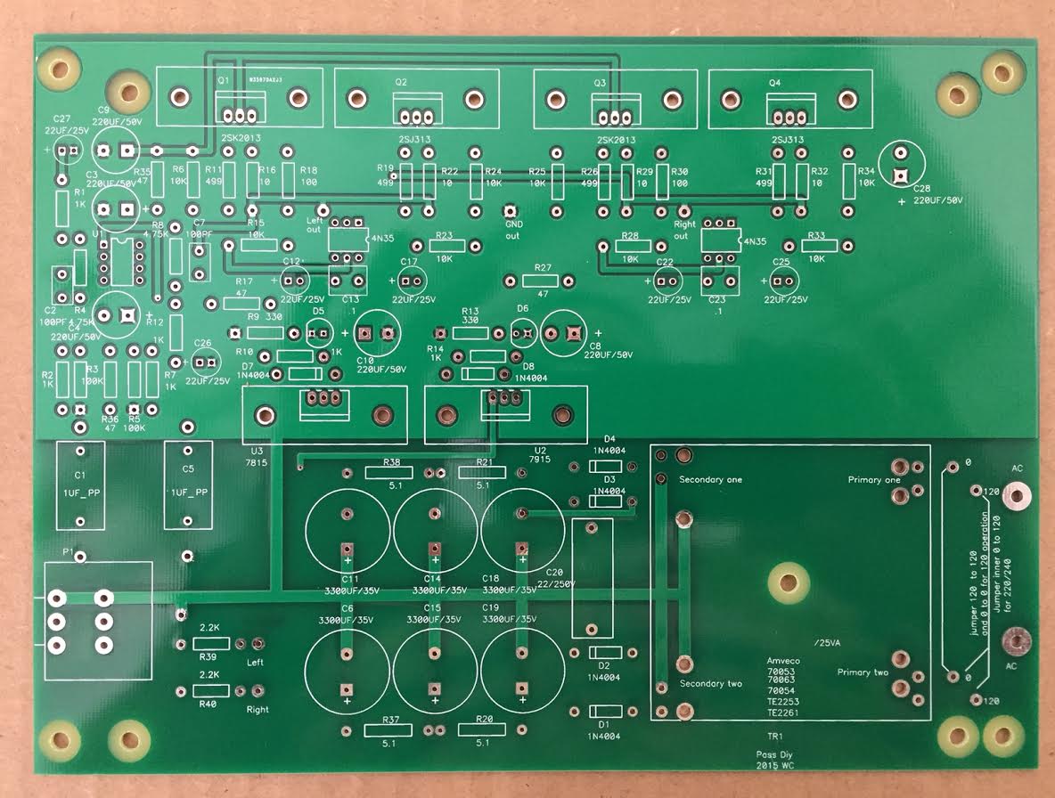
Hi 6L6, how different is this board (Rev.3) from the Gerber published by Wayne, except for R39 & R40 (2.2K resistors at input)... I have got the PCB made from the Gerber and I am not able to tell any difference...except what I highlighted... I read somewhere these 2 resistors are to manage possible oscillations, so is this the only change to the earlier boards??Rev.3
Cool!!
Ive just built a WHAMMY for a non DIYer, alls well apart from a strange 'very faint' audible POP/CLICK at (9:00 o'clock) as the vol is turned up/down. It's only on the right channel.?? Ive swapped out the pot for a new one but the 9:00 o'clock POP is still present. Sounds great, its just annoying. op-amps are OPA627BPs. Ive built a few priviously and those turned out great with no issues.
Any ideas Guys.
TIA
Any ideas Guys.
TIA
Last edited:
Ive just built a WHAMMY for a non DIYer, alls well apart from a strange 'very faint' audible POP/CLICK at (9:00 o'clock) as the vol is turned up/down. It's only on the right channel.?? Ive swapped out the pot for a new one but the 9:00 o'clock POP is still present. Sounds great, its just annoying. op-amps are OPA627BPs. Ive built a few priviously and those turned out great with no issues.
Any ideas Guys.
TIA
Scratch my request..the right channel op-amp has issues.. Swapped it and all is well now.
Quick question.
Are all 4N35 optocouplers the same?
I can get these for a very decent price:
https://www.mouser.co.za/ProductDetail/Toshiba/4N35SHORTF?qs=EEns8I54Y6CfHc6h1NSnmQ==
What do the mean by 'SHORT'? I can't figure this out.
Are all 4N35 optocouplers the same?
I can get these for a very decent price:
https://www.mouser.co.za/ProductDetail/Toshiba/4N35SHORTF?qs=EEns8I54Y6CfHc6h1NSnmQ==
What do the mean by 'SHORT'? I can't figure this out.
Last edited:
- Status
- This old topic is closed. If you want to reopen this topic, contact a moderator using the "Report Post" button.
- Home
- Amplifiers
- Pass Labs
- New PassDIY Headphone Amp (now available)