Finished the amp and am quite happy with it. I am going to give it to my son for Christmas
Nice work.
Your enclosure has a simple elegance -- is it commercially available or did you fabricate it?
Hello,
asking for help - and advice.
1) I'm using Takman Resistors for the amp - Can I use 510R instead of 499R in position R11, R19, R25, R31 and can someone explain me, how I could figure this out by myself?
2) Can someone help me and explain how to connect earth and grnd properly?
3) Where should I connect GRND from the INPUT for left and right channel?
3.1) All Star grounded and Earth connected to Star ground as well?
4) Q1-Q4 - shall the parts be isolated from the heatsinks?
Sorry for the stupid questions, but haven't done that much projects yet.
many thanks and best regards, tom
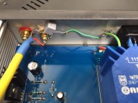
Somewhere in a post I remember Wayne saying that the board ground should be tied to chassis ground through a .1uf capacitor. I scraped some of the green paint off the large ground pad on the bottom of the board and soldered the capacitor to it and ran a lead to chassis ground. Remember to tie the ground from the AC mains to chassis ground. Safety first.
You want a hard ground to the chassis from the AC ground and then .047 - .22 from chassis to in put connector. The transistors don't need isolation or insulators as long as the sinks don't touch the chassis. Some of the available transistors are fully epoxy isolated and that makes it easy.
")
the quiescent current of my amplifier is 100 mA at 10 ohms and 45 mA at 22 ohms.
Very heated radiators output transistors.
How else can the output current of the output transistors be reduced?
You could reduce the center 10K divider resistors. What output transistors?
- Status
- This old topic is closed. If you want to reopen this topic, contact a moderator using the "Report Post" button.
- Home
- Amplifiers
- Pass Labs
- New PassDIY Headphone Amp (now available)