No they aren't all the same but from what I have tried they all seem to work.
The bias may have some variation but none have caused fires.
Thanks Wayne. Will do. It does seem that the transfer specs are different, so will probably affect the biasing.
A Whammy build tale
I completed my Whammy build yesterday and thought I would share some thoughts and pictures. My main use will be listening to music while working at my desk. Right now I am streaming Tidal through a Grace SDAC which sounds pretty darned good for a budget rig especially with a “Master” quality file. First and fundamentally - many thanks to Jim (6L6) for the build guide and to Wayne for giving us a great design to work with. Their ongoing support of the DIY Audio community makes it a heck of a lot easier to have a successful build.
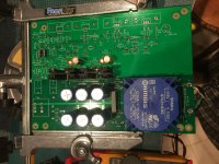
My Whammy went together easily, and worked almost without incident. There was one brief moment of panic when I first fired it up and heard a strong 60 Hz hum in both channels and low output in one. After a deep breath or three, I started troubleshooting and found the 3.5mm jack feeding the Whammy was not plugged all the way in to the SDAC. Sometimes the solution really is that simple.
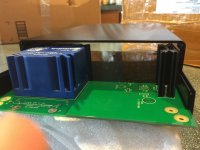
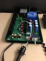
I used a 1706 enclosure from AliExpress but payment was kind of a pain in the neck due to security alert issues from my bank (took three times to get it to go through). I later found the enclosures are also available on Ebay which is much easier at least in the US - just do a search for 1706 enclosure. When I scaled the dimensions of the enclosure off the AliExpress drawing it looked be very close to the height of transformer and heatsinks (1.5"/37.5 mm). Fortunately, everything fit fine - see picture below. Also, the enclosure is slightly too wide and so the board can fall out of the groove on one side or the other. I added some standoff feet and solved this minor issue. Some tape on the corners of the board also works to take up the extra space and keep the board cented and in the grooves. The enclosure did not come with any hardware but a quick stop at the hardware store solved that issue. Overall, I like the enclosure and would recommend it for this project.
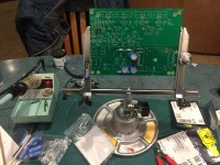
In terms of components I pretty much followed the build guide and got everything, other than output transistors, from Mouser on a single order. I did use fast recovery diodes throughout and purchased some extra / alternate caps (Nichicon, Panasonic, and Silmic II) to try swapping different caps in and out – if I get around to it. Some op amp rolling also seems likely in the future so the op amp is socketed. The transformer is +/- 15Vac, the Op amp is OPA2134PA and the output transistors are Toshiba 2SK2013 / 2SJ313 from my dwindling stash.
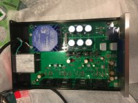
Also, I added a Schurter filtered, fused, and switched AC input module. It is the largest single cost in the project and probably overkill. I had great luck with it on my Pearl 2 (silent) and Pass uses filtered input modules on their preamps so I figured I should use one here too. The input module is big so it only really fits in one spot - but it does fit. Cutting the hole for the input was the hardest part of the project. I made a paper cardstock template of the backplate to make sure everything fit. I then put masking tape on the backplate and transferred the layout from the template to the backplate. I pre-punched then drilled some holes in the diagonally opposite corners and used a fine-toothed metal jigsaw blade to make the cutout. FYI – I always cut a little bit inside the lines and then file to final fit. This takes longer but insures a good fit.
Other than listening to music , my next step is the pick a volume knob – far too many choices to make an easy decision. Also, if and when I start op amp / capacitor rolling I will also probably update to some better internal wire for the RCA jacks to PCB and PCB to the headphone jack.
I completed my Whammy build yesterday and thought I would share some thoughts and pictures. My main use will be listening to music while working at my desk. Right now I am streaming Tidal through a Grace SDAC which sounds pretty darned good for a budget rig especially with a “Master” quality file. First and fundamentally - many thanks to Jim (6L6) for the build guide and to Wayne for giving us a great design to work with. Their ongoing support of the DIY Audio community makes it a heck of a lot easier to have a successful build.
My Whammy went together easily, and worked almost without incident. There was one brief moment of panic when I first fired it up and heard a strong 60 Hz hum in both channels and low output in one.
After a deep breath or three, I started troubleshooting and found the 3.5mm jack feeding the Whammy was not plugged all the way in to the SDAC. Sometimes the solution really is that simple. I used a 1706 enclosure from AliExpress but payment was kind of a pain in the neck due to security alert issues from my bank (took three times to get it to go through). I later found the enclosures are also available on Ebay which is much easier at least in the US - just do a search for 1706 enclosure. When I scaled the dimensions of the enclosure off the AliExpress drawing it looked be very close to the height of transformer and heatsinks (1.5"/37.5 mm). Fortunately, everything fit fine - see picture below. Also, the enclosure is slightly too wide and so the board can fall out of the groove on one side or the other. I added some standoff feet and solved this minor issue. Some tape on the corners of the board also works to take up the extra space and keep the board cented and in the grooves. The enclosure did not come with any hardware but a quick stop at the hardware store solved that issue. Overall, I like the enclosure and would recommend it for this project.
In terms of components I pretty much followed the build guide and got everything, other than output transistors, from Mouser on a single order. I did use fast recovery diodes throughout and purchased some extra / alternate caps (Nichicon, Panasonic, and Silmic II) to try swapping different caps in and out – if I get around to it. Some op amp rolling also seems likely in the future so the op amp is socketed. The transformer is +/- 15Vac, the Op amp is OPA2134PA and the output transistors are Toshiba 2SK2013 / 2SJ313 from my dwindling stash.
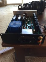
Also, I added a Schurter filtered, fused, and switched AC input module. It is the largest single cost in the project and probably overkill. I had great luck with it on my Pearl 2 (silent) and Pass uses filtered input modules on their preamps so I figured I should use one here too. The input module is big so it only really fits in one spot - but it does fit. Cutting the hole for the input was the hardest part of the project. I made a paper cardstock template of the backplate to make sure everything fit. I then put masking tape on the backplate and transferred the layout from the template to the backplate. I pre-punched then drilled some holes in the diagonally opposite corners and used a fine-toothed metal jigsaw blade to make the cutout. FYI – I always cut a little bit inside the lines and then file to final fit. This takes longer but insures a good fit.
Other than listening to music
, my next step is the pick a volume knob – far too many choices to make an easy decision. Also, if and when I start op amp / capacitor rolling I will also probably update to some better internal wire for the RCA jacks to PCB and PCB to the headphone jack.Attachments
-
 Height check.JPG558.5 KB · Views: 764
 -
 Stuffing parts.JPG809.9 KB · Views: 760
 -
 Power supply works.JPG753 KB · Views: 756
 -
 Input module.JPG797 KB · Views: 754
 -
 It's alive.JPG554.3 KB · Views: 660
 -
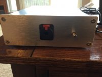 Front panel done.JPG511.5 KB · Views: 323
 -
 Back panel done.JPG573.3 KB · Views: 293
 -
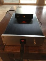 Sounding great.JPG503.1 KB · Views: 277
Cap choices - what, where and why
Thank you - It was an easy and fun project.
I realize folks can become obsessed with parts selection when it really doesn't matter or can simply be a case of "this is what I had in my parts bin"
That mea culpa aside, I have one quick questions on caps to satisfy my curiosity...
In looking at the build guide I think you used Nichicon UFG series ? at C3, C4, C9 and C28 but something else (Panasonic FM ?) at C8 and C10.
I was wondering if you remembered what part you used for C8 and C10 and why ?
Was it :
- I had a couple old ones lying around and wanted to use them up.
- Use anything there since doesn't don't matter in that location.
- Some other reason, based on long experience, that I am not seeing.
I used Nichicon UFG at all those locations because they were easy to order while I was at it. I have several other options in my parts bin that I could play with Panasonic FM, Elna Silmic II, Nichicon, etc. if there might be a reason to swap them out.
Regards, J
Beautiful! Well done and congratulations!!!
Thank you - It was an easy and fun project.
I realize folks can become obsessed with parts selection when it really doesn't matter or can simply be a case of "this is what I had in my parts bin"
That mea culpa aside, I have one quick questions on caps to satisfy my curiosity...
In looking at the build guide I think you used Nichicon UFG series ? at C3, C4, C9 and C28 but something else (Panasonic FM ?) at C8 and C10.
I was wondering if you remembered what part you used for C8 and C10 and why ?
Was it :
- I had a couple old ones lying around and wanted to use them up.
- Use anything there since doesn't don't matter in that location.
- Some other reason, based on long experience, that I am not seeing.
I used Nichicon UFG at all those locations because they were easy to order while I was at it. I have several other options in my parts bin that I could play with Panasonic FM, Elna Silmic II, Nichicon, etc. if there might be a reason to swap them out.
Regards, J
It's my first post. I assembled this project and I've got a problem. After switching on, supply voltages decrease to +/- 10V (originally +/-15V) and on output I have -3,8V on both channels. When I unplug one of supply connectors second voltage is back to normal value? All parts are soldered correctly and have correct values. I thought maybe it's a problem with opamp but no (I changed to others and nothing happen). Transistors 2SK2013, after 2-3 minutes are very hot (2SJ313 are cold) It looks like bad gate voltage maybe or something else?
The latest were not released. These are the only supplied ones here and in my eyes they are similar to the sold ones except the input resistors. This is DIY, so adding them should not be an issue ;-). When the box later is closed, you will see and hear no difference. And you might forget about it. Have a nice Sunday.
Dear Ernesternest,
Thx for your answer to let me how to do. just adding two 2.2K and then nothing else.
Unfortunately, my Eagle PCB cant open the gbr correctly, i think it is a bug and trying use other apps to open it.
PCB gbr viewer website can open it correctly but can't edit it.
Thx for your answer to let me how to do. just adding two 2.2K and then nothing else.
Unfortunately, my Eagle PCB cant open the gbr correctly, i think it is a bug and trying use other apps to open it.
PCB gbr viewer website can open it correctly but can't edit it.

An externally hosted image should be here but it was not working when we last tested it.
As the machine not support some GBR files which got from the old post link. (some file missed)
So for more fun, re-make it!
As i know this AMP is a commercial product and selling on website, So i have not add the 2.2K Resistors on the source input.
- Status
- This old topic is closed. If you want to reopen this topic, contact a moderator using the "Report Post" button.
- Home
- Amplifiers
- Pass Labs
- New PassDIY Headphone Amp (now available)