Any recommendation for single op amp?
Hmm...this has been asked before in post 663. Did you not read back that far? If not, I can't blame you as I sometimes don't read through enough previous posts for a given thread.
")
Anyway, I made a few recommendations in post 665. If those don't work for you, feel free to try whatever single channel op-amp you like.
Good luck with your build and I like the PCB you designed.
post-processing and ordering...
JP
Good to see you back in action.
I admire the way churn out pcb designs.
Hello @anmel68
It´s a month ago!
My list before ordering:
- OPA627, not cheap
- OPA134
- OPA604
- LME49710
- SS OPAMP V5
- MUSES03 cost an arm
4 boards coming end of next week...
JP
Arms are over rated. Who needs 2 arms.
Hello @anmel68
It´s a month ago!
My list before ordering:
- OPA627, not cheap
- OPA134
- OPA604
- LME49710
- SS OPAMP V5
- MUSES03 cost an arm
By the way...it's ammel68, not anmel68.
Well...there you go! You're "before ordering" list is pretty good, though there are some better options like the ADA4627-1 like I've pointed out before.
Should you find a better sounding FET input op-amp than the '4627-1, let me know because I've got to try it!
Whether or not it sounds magical in this design, I have no idea.
I've never tried the MUSES03, nor do I plan on giving up one of my arms to do so.
Some of the dual channel NJR offerings are pretty good IMO.
The LME49710/20/LM4562 has never really done anything for me with their "sterile" and "lifeless" sound.
I threw all of mine in the trash.
But...this type of sound may appeal to you.
Good luck with your op-amp "rolling" and report back soon with your findings.
Last edited:
Hi Alvinlim,
start reading around post #329 on page 33
and #388 on page 39
http://www.diyaudio.com/forums/pass...headphone-amp-coming-soon-33.html#post4597417
Question on R9, R13 : If I am using +/- 15v rails with LED, do I remove R9 and R13 and leave them open? My understanding is that I do not short R9 and R13. Is this correct?
Thanks
start reading around post #329 on page 33
and #388 on page 39
http://www.diyaudio.com/forums/pass...headphone-amp-coming-soon-33.html#post4597417
Last edited:
wayne
Are there still some more PCBs on the way?
Would like to get myself a PCB or 2.
Hi,
I put in my order and almost forgot about it about 2 mo. and BAM! a paypal notice was in my inbox I paid and a few days later a green board appeared in my mailbox,I understand he is busy with this and PL is busheling with some new amps,so give him some time and "THE WIZZARD ASSISTANT" might do a magic trick for you
and if he does Thank him,I did
New PassDIY Headphone Amp (Coming Soon)
Thanks but I couldn't find any reference to R9 and R13 for those pages and the subsequent 3-4 pages. To put my question in context, in the schematics, there is a note stating "R9, R13 at 330 ohms give +/- 21.5 volts with no D5 and D6. If using D5 and D6 Leds, omit R9 and R13. R9 and R13 may be shorted for +/- 15". So, if I am using LEDs, does it mean I leave R9 and R13 open?
Thanks again
(Ref post #733)
Last edited:
hi,Thanks but I couldn't find any reference to R9 and R13 for those pages and the subsequent 3-4 pages. To put my question in context, in the schematics, there is a note stating "R9, R13 at 330 ohms give +/- 21.5 volts with no D5 and D6. If using D5 and D6 Leds, omit R9 and R13. R9 and R13 may be shorted for +/- 15". So, if I am using LEDs, does it mean I leave R9 and R13 open?
Thanks again
My board is partly together I am waiting on parts I have 15 v regs R13 and R9 are 5 ohms, I read in # 338 R16-22-29-32 need to be 5R also, you can omit R10-C10-D5 and JR9 I have not tested this yet,When I can test this I will, but most people say they are ending up with 17.5 volts with stock parts on bom.Feel free to correct this if it's wrong
The led won't work ,but you can rewire it with a resistor inline to the reg output and make it work,you can find a LED cal online to make it dim or bright,I hope this has helped you.
Last edited:
The LEDs in the regulators are not light bulbs.
They are being used as low-voltage zeners, and using them will increase the output voltage by the Vdrop of the LED.
Remember these are fixed regulators, not 317/337, so you don't have to use resistors to set the output voltage. (But you can...)
Do you want 15V?
Use a jumper in R9 (so pin 2 of the regulator finds ground) Leave the LED, Capacitor, and other resistor (R10) open. This is the regulator in it's native voltage.
Want 17.4V?
Use a red LED in the LED position, leave R9, R10 open, and if you like use a capacitor from 10uF-220uF, or leave empty. The regulator is now "standing" on top of the voltage from the LED and the output will be the LED Vdrop+15v. want a few more tenths of a volt? Use a green LED instead of red. Cheap normal LED are extremely quiet voltage references, but high brightness blue and purple are reported to be noisy. The bypass capacitor is used to help quiet even further.
Want 21.5V?
Use R9 330ohm and R10 1K ohm, leave the LED open, and use the capacitor if you want, or leave empty. This is using the resistors as a voltage divider to make the output voltage higher, similar to how a 317 is set. The bypass capacitor is for noise and can be used or omitted. The new boards show different resistor/voltage combinations I believe.
Of course, do the same in the positive channel and the negative channel, but watch your polarity!
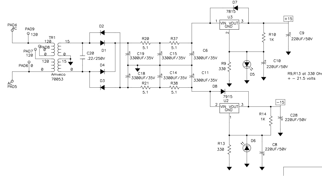
Lastly, use D7, D8 always, they are protection diodes for the regulators when any/all of the downstream capacitors discharge.
They are being used as low-voltage zeners, and using them will increase the output voltage by the Vdrop of the LED.
Remember these are fixed regulators, not 317/337, so you don't have to use resistors to set the output voltage. (But you can...)
Do you want 15V?
Use a jumper in R9 (so pin 2 of the regulator finds ground) Leave the LED, Capacitor, and other resistor (R10) open. This is the regulator in it's native voltage.
Want 17.4V?
Use a red LED in the LED position, leave R9, R10 open, and if you like use a capacitor from 10uF-220uF, or leave empty. The regulator is now "standing" on top of the voltage from the LED and the output will be the LED Vdrop+15v. want a few more tenths of a volt? Use a green LED instead of red. Cheap normal LED are extremely quiet voltage references, but high brightness blue and purple are reported to be noisy. The bypass capacitor is used to help quiet even further.
Want 21.5V?
Use R9 330ohm and R10 1K ohm, leave the LED open, and use the capacitor if you want, or leave empty. This is using the resistors as a voltage divider to make the output voltage higher, similar to how a 317 is set. The bypass capacitor is for noise and can be used or omitted. The new boards show different resistor/voltage combinations I believe.
Of course, do the same in the positive channel and the negative channel, but watch your polarity!
Lastly, use D7, D8 always, they are protection diodes for the regulators when any/all of the downstream capacitors discharge.
Last edited:
- Status
- This old topic is closed. If you want to reopen this topic, contact a moderator using the "Report Post" button.
- Home
- Amplifiers
- Pass Labs
- New PassDIY Headphone Amp (now available)