Thanks Jim.
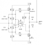
Here's my crazy idea: I built the BA-3 front end as a preamp. I need a headphone amp and the BA-3 FE doesn't cut it for my Grados. I am thinking I need to add an output stage to the BA-3 for headphone use. The output stage from this headphone amp looks promising.
I want to run the BA-3 front end straight into the output stage and keep it all in the same case and (hopefully) use the same 24V+/- PSU. Sound like a good plan? Worst case scenario I can set up a second reg at 15V for the output stage if 24V isn't a good idea.
I can see some sort of feedback loop on the output back to the IC on this headamp. I would not have that in my BA-3 plus output stage scenario. Any issues with that? I am guessing it's just for feedback use in the IC and I could ignore it.
Attachments
> Here's my crazy idea: I built the BA-3 front end as a preamp. I need a headphone amp and the BA-3 FE doesn't cut it for my Grados. I am thinking I need to add an output stage to the BA-3 for headphone use. The output stage from this headphone amp looks promising.
Your idea ?
http://www.diyaudio.com/forums/pass-labs/271926-f5-headamp-7.html#post4523035
Patrick
Your idea ?
http://www.diyaudio.com/forums/pass-labs/271926-f5-headamp-7.html#post4523035
Patrick
The output impedance is higher without feedback but you could try it.
Hi Wayne.
I've been pondering a turbo preamp/buffer to drive BAF mu follower amp.
I'd be happy with anything between unity gain and 6dB (no more than that), DC coupled and output impedance of no more than 50 Ohms
Would this headamp make for a decent turbo preamp?
Well they are pretty much the same some just have more circuitry. The Muse and the Maxim1882 are two I have used successfully. The board is set up to use the Alps 27 Mm pot.
What about Muses 72320?
You don't need the feedback loop. The output stage performs perfectly without feedback.I can see some sort of feedback loop on the output back to the IC on this headamp. I would not have that in my BA-3 plus output stage scenario. Any issues with that? I am guessing it's just for feedback use in the IC and I could ignore it.
Thank you
It is my work
There is also a implemantation for 7 Segment Display from adafruit...
")
I had been thinking of doing one of these but seems like you have already done a great job.
No point reinventing the wheel, are you selling these?
Hi,
i will build the Amp.
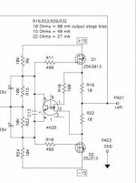
Can someone mark drain and source of q1 and Q2 in the attached shematic for me ?
I am confused. Is the shematic correct ? The N Type at +15V and the P Type at -15V?
Thanks!
Daniel
i will build the Amp.
Can someone mark drain and source of q1 and Q2 in the attached shematic for me ?
I am confused. Is the shematic correct ? The N Type at +15V and the P Type at -15V?
Thanks!
Daniel
Attachments
Last edited:
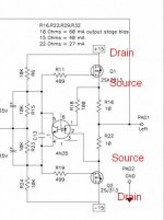
Q1 has the arrow pointing IN towards the gate. That means it is an N channel mosFET. The K of 2sk also confirms it is N channel.
Two of the three outputs are connected together. These are the Source lead.
The single output is the Drain.
The gate is offset to the bottom side. This also ends up drawn opposite the source.
All of the above mosFET drawing conventions tell you that the drain is at the top and the source is at the bottom.
The opposite orientation applies to the Pchannel mosFET.
It has the drain at the bottom and the source at the top. The gate is still opposite the source.
Lateral mosFETs have the source as the middle pin of the plastic package.
Vertical mosFETs have the drain as the middle pin of the plastic package.
- Status
- This old topic is closed. If you want to reopen this topic, contact a moderator using the "Report Post" button.
- Home
- Amplifiers
- Pass Labs
- New PassDIY Headphone Amp (now available)