ok... after re-reading your post i think you meant that the pre alone lacked dynamics, which you compensate with the intregration of a power stage to drive speakers, notably the attached attached schematic...
Still that Sigma22 is a nice piece of circuitry in my opinion if someone wants more oomph than cap bank...
Still that Sigma22 is a nice piece of circuitry in my opinion if someone wants more oomph than cap bank...
Last edited:
Yes, the no-feedback-loop version lacked that last step in definition and clarity, although it's just the way I hear it - many popular designs lack 3 or more steps in that direction and no one objects, so I suppose it's not that important to most listeners. One can have fun listening to music in so many ways...
As for power supply - to keep the output stage bias stable, both sets of rails need to be regulated.
As for power supply - to keep the output stage bias stable, both sets of rails need to be regulated.
Last edited:
As for power supply - to keep the output stage bias stable, both sets of rails need to be regulated.
yes thanks for reminding that with that much gain, a stable symetrical voltage supply is needed. At that point matching and thermal coupling should also be beneficial. This toplogy makes me think of walking on a rope with arms attached in the back!
Also, the low psrr of the output stage looks like it need to be accounted for, if i'm not mistaken...
BTW , if i may, what supply do you use for this amp?
Yes, the circuit from BAF 2013 is really special and its worth an effort to turn it into power amp with enough gain and Zin high enough so that preamp is not needed any more.
It has that wonderful gentle seductive touch, live and involving character - it's one of the very rare no-feedback-loop circuits that can successfully reproduce much more than just a girl & guitar type of music.
It definitely has a special charm and it only lacks that last step in definition and clarity with complex orchestral music.
Since it stays linear with higher gain settings I tried to overcome that by using different output stage and feedback variations, using Laterals (k1058/j162) and Sony's VFETs (k60/j18) in common source and common drain configurations (with appropriate biasing and feedback settings) and it's not very hard to find a spot where everything sits perfectly.
I listen to it since last autumn and it still thrills me. I prototype and test different stuff all the time, listen to various equipment owned by buddy audiophiles, but this one stays....
Hi Juma,
Very interesting your comments on the attached schematic. Can you show the component value? Thank you in advance.
Regards,
Boyet
It's easy to make different version of this amp (MOSFETs or VFETs in output stage, common source or common drain configuration, JFETs or BJTs at input and/or cascodes, etc.) which makes the field for experimenting very wide but let's say you want the schematic from post #199. Calculating the values is trivial if we put together what we already know:
- We want JFETs Id set at 80-90% of Idss. How much is that ? I don't know - it depends on JFETs you have at hand. They come in wide range so you got to measure them.
- JFETs' Vds can't be more than 25V but it can be less since we have common source output stage
- Cascodes need 5-10 mA flowing through them (let's calculate for 8 mA and small practical deviations won't matter)
- CCS carries the sum of currents through JFET and the cascode
- CCS needs about 5V to function properly
- Lateral MOSFETs need the Id of at least 0.5A (1A is preferable) to sound good which usually translates to Vgs of 1.5V to 2V (depending on parts you have at hand so you got to measure them)
- gain cell is a gm stage so it's good to give it some load in order to define its behavior
- amp's gain can be set in 15-30dB range, depending on your needs
- practical build will determine if you need some freq. compensation and how much of it.
So if we know basic characteristics of parts used (Borbely's article about JFETs and Mr. Pass' article/manual on F5) it all becomes an easy task...
In schematic post 1,
i guess there is no harm putting a trimpot in parallel with r11 to set dc offset along with p1 and aleviate the burden on the jfets?
(Especially as the value of r25 goes down )
My guess is that it would result in higher 2nd harmonic distortion as one half contributes less to the output signal, but not in a really harmful way if we are talking less than a mA difference...
Alternatively, I'm thinking of an adjustable jfet CCS installed from q1 or q2 drain to ground, again to set a different current for q6 or q7 and thus adjust DC offfset.
R11 is a sensitive spot - it would have to be either 1M in parallel or 10-20R in series (with R11 set to 56R - 62R ).In schematic post 1, i guess there is no harm putting a trimpot in parallel with r11 to set dc offset along with p1 ...
Then you can use P1 to fiddle minimal/preferable distortion.
ok..i received my laterals and been playing with a few configurations.
i'm still toying so i don't have a final setup and appreciation to give yet, but what i found was the following:
-version with current mirror as per post number 1 gave oscillations i believe (because of wierdd sound) , without feedback and with laterals, so i can't comment and will have to make a better layout first.
-i made a «lazy cat TSSA-style» amp with laterals and it works pretty well, though i missed somewhat the no-feddback sound that i cherish.
-the best sound i have so far is with «lsk-pre with ccs» then a simple irf610 follower buffer driving an f4 (removing it's own buffer). I,ve tried pair of comp. jfet, as well as comp. bjt , and comp. mosfet ....but the simple SE mosfet follower gives me the best overal sound up to now and gives great punch to the f4. It also has the advantage of accepting higher supply voltage from lsk pre.
i alos tried the laterals in the f4 (which i prefer overall over the irfp240/9240), but i had to put the irf because i needed sound and they sounded too high pitched with the stetup i place....so i will eventually do more testing with these lat.fet.....
very fine piece of OP. stage transistor they look like those 2sk1058/j162! they are very detailed all across the spectrum.
Last edited:
Cubie AB 20W
Hi everyone and Juma. It would be possible to build a simple Cubie(Cubiezilla?) with a jfet pair input (k170-K366 / J74-J108), VAS bc550/560 and output Lfet K58/J62 power between 15 and 20WRMS in 8 ohms, class AB. I have multi amplification and would like to try an amplifier like this for medium speaker(Vifa) and high (RT Fountek). Thank you for your help.
Hi everyone and Juma. It would be possible to build a simple Cubie(Cubiezilla?) with a jfet pair input (k170-K366 / J74-J108), VAS bc550/560 and output Lfet K58/J62 power between 15 and 20WRMS in 8 ohms, class AB. I have multi amplification and would like to try an amplifier like this for medium speaker(Vifa) and high (RT Fountek). Thank you for your help.
Sure it is possible.... possible to build a simple Cubie(Cubiezilla?) with a jfet pair input (k170-K366 / J74-J108), VAS bc550/560 and output Lfet K58/J62 power between 15 and 20WRMS in 8 ohms, class AB...
What is the Idss of your JFETs at Vds=20V ?
Sure it is possible.
What is the Idss of your JFETs at Vds=20V ?
Hi Mr. Juma and all: sorry, I'm newbie to audio and electronics. So, only I like this a lot. My request for help is because I have tracked several threads about VSSA and it seems to be positive opinion that the input is JFET (detailing and low noise), the BC550 / 560 due to low noise and the LFET output because they were designed to play audio, very close to the sound of tube. So I figured that 20 WRMS / 8Ohm is good power for multiple Xover active systems and special amplifier for each speaker. I also want to try changing this amp to transconductance (current). It looks a lot like tube sound, of course, much cheaper to build. Can you help anyway, please?
Upping the output power of Cubie2 to 20W@8R is not a big deal - just a few values need changing. That is why I asked you about Idss of your JFETs.
The rest of your wishes/ideas/assumptions show lack of experience and I think you should go at it slowly, step by step, until you really know what you want.
Maybe you should start with something more popular, something that many others have already built....
The rest of your wishes/ideas/assumptions show lack of experience and I think you should go at it slowly, step by step, until you really know what you want.
Maybe you should start with something more popular, something that many others have already built....
Dear Juma: I appreciate your help. I leave transconductance matter aside. I think I mixed two different subjects. But I insist: Could a new Cubie simpler, modeled with only 6 semiconductors: two jfets input, pair BC550/560 VAS and an output with K1058 and J62, in class AB, powered with 25VDC close to 20W @ 8ohms? Thank you again.
Dear Juma: I appreciate your help. I leave transconductance matter aside. I think I mixed two different subjects. But I insist: Could a new Cubie simpler, modeled with only 6 semiconductors: two jfets input, pair BC550/560 VAS and an output with K1058 and J62, in class AB, powered with 25VDC close to 20W @ 8ohms? Thank you again.
Maybe beta22 by amb.org is a bit like what you are describing...?
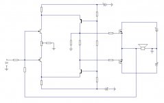
Nice 6-transistor variation of this idea can be done with Curl-ish symmetrical folded cascode as transconductance gain stage (with variable OLG) plus source-follower output stage, all nicely wrapped in controlling loop.
It can be done with common-source output stage too, with one or two sets of power supply rails, with or without feedback loop (local or global, low or high Z), etc. - it can be varied in many ways so no values are shown, just a somewhat simplified diagram.
It can be done with common-source output stage too, with one or two sets of power supply rails, with or without feedback loop (local or global, low or high Z), etc. - it can be varied in many ways so no values are shown, just a somewhat simplified diagram.
Attachments
Last edited:
Source follower is common drain connection - exactly as shown.
You probably mean common source OPS, where output is taken from the drains, to provide voltage and current gain and you also probably mean Transnova-like OPS. There are few other ways to do it - a matter of preference...
You probably mean common source OPS, where output is taken from the drains, to provide voltage and current gain and you also probably mean Transnova-like OPS. There are few other ways to do it - a matter of preference...
- Home
- Amplifiers
- Pass Labs
- Cubie2