Howy Diynosaurs,
i need your help. After a long abscence i am back in the Hifi Diy. Since i am writing my master thesis i needed something to clear my head... so why not build a headphone amplifier. My Yamaha C2a (great preamp for my F5) has no headphone output. Great lets do this.
Looking through various circuits on the net i decided it had to be simple and parts must come from the parts bin. I found a lot of 2K170 in the basemnet. Great lets use these, if papa can drive speakers with them then it must e possible to drive a headphone with the too.
So here are the design goal:
Battery Operated (12v) because i have 12V Battery left over
2Sk170 as output device
Class A
little to no Phase shift
Must be able to Drive low Impedance Headphones like the Shure SR840 to 110 db with little distorsion and some headroom left.
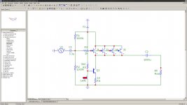
So here is the first prototype i came up with in simulation. A Jfet common drain current buffer. Distorsion seems ok in simulation, but testing a prototype channel with some cheapo earphones distorsion seemd a little highher. But in general, great sound even with the elko.
So where to go from here? I could bias the Jfets even higher als long as i stay probably up to 3000mw dissapation per jefet, add more jfets maybe up to ten, but i will need more bc550 in the current sink because the single one is already at its limits.
And there is one problem i have. When powering the unit or connecting the headphones i get a quite loud pop in the headphones, i guess the elko cap is discharging through the headphones, what can i do about this?
i need your help. After a long abscence i am back in the Hifi Diy. Since i am writing my master thesis i needed something to clear my head... so why not build a headphone amplifier. My Yamaha C2a (great preamp for my F5) has no headphone output. Great lets do this.
Looking through various circuits on the net i decided it had to be simple and parts must come from the parts bin. I found a lot of 2K170 in the basemnet. Great lets use these, if papa can drive speakers with them then it must e possible to drive a headphone with the too.
So here are the design goal:
Battery Operated (12v) because i have 12V Battery left over
2Sk170 as output device
Class A
little to no Phase shift
Must be able to Drive low Impedance Headphones like the Shure SR840 to 110 db with little distorsion and some headroom left.
So here is the first prototype i came up with in simulation. A Jfet common drain current buffer. Distorsion seems ok in simulation, but testing a prototype channel with some cheapo earphones distorsion seemd a little highher. But in general, great sound even with the elko.
So where to go from here? I could bias the Jfets even higher als long as i stay probably up to 3000mw dissapation per jefet, add more jfets maybe up to ten, but i will need more bc550 in the current sink because the single one is already at its limits.
And there is one problem i have. When powering the unit or connecting the headphones i get a quite loud pop in the headphones, i guess the elko cap is discharging through the headphones, what can i do about this?
Attachments
A few Pass designs over here as B1 and few others are a text book example circuits, so you have nothing to be ashamed for. My advice is to insert say about 4.7 Ohm source resistors at each of the jfet sources so you could measure how`s the current sharing between jfets It could be important if they`re not matched. Also you could try lower value R3, let`s say 100-220 ohms because of paralleling jfet`s Cgd-s and you could also lower input coupling cap, for a 500K input impedance (run the AC analysis in MCAP, All that things you could check in simulator with the good accuracy.) but It` won`t change the sound if the capacitor type is the same.
I guess you ment 300mW per jfet, that`s ok but don`t go over that, 200 - 250mW is a better choice. BC550 should be thermaly coupled to LED etc and you could change it to BD139 to be on the safe side. . Everything will work even the wat you draw but better to do it right and it`s not so complicated.. Cheers!") Try bypassing output elco with film cap for sound tuning etc...
Try bypassing output elco with film cap for sound tuning etc...
I guess you ment 300mW per jfet, that`s ok but don`t go over that, 200 - 250mW is a better choice. BC550 should be thermaly coupled to LED etc and you could change it to BD139 to be on the safe side. . Everything will work even the wat you draw but better to do it right and it`s not so complicated.. Cheers!
Try bypassing output elco with film cap for sound tuning etc...When powering the unit or connecting the headphones i get a quite loud pop in the headphones,
i guess the elko cap is discharging through the headphones, what can i do about this?
Good luck. Just add a resistor at the output after the coupling capacitor of around 1k Ohms to stop the popping.
Razor,
That won't work very well. To prevent oscillations you need a gate stopper on every JFET's gate, and to prevent current hogging you need a resistor in every JFET's Source. You need a resistor to discharge the output and input cap. Also, you need a fillter on voltage divider at JFET's gates - battery is not so clean as one might think. Also, the CCS (Q5) to supply the LED Vref should be used. Five instead of four Source Followers JFETs is better (10 is even better).
You don't write what is the grade of your JFETs (GR, BL or V) but use the highest Idss parts you got and set the P1 so that you get about 80-90% of Idss through every Source Follower JFET (measure the voltage drop on 4R7 Source resistors).
If you got, for example, JFETs with Idss=10mA you'll wan't to run about 9mA through each of them, so the Q6 CCS should supply about 40-45mA (if you use 5 JFETs as in my sch.). The LED used should be nothing fancy, ultra bright etc., just plain old, 3mm red one. If Q6 gets hot, use the bigger one - BD139 or similar.
Viel Spass !
Edit: there's an error - the resistor in Q7's Drain shouldn't be there, that Drain should connect straight to +12V
Attachments
Last edited:
Looking at your current source isn't it set fore about 130 ma ?
I don't think 4 of the 2sk170 will do anything any where near
that. Now what might be neat is the Ld1014d power jfet instead
of the 2sk170's.
Yes I did`nt noticed that and low load (44 ohms) so 4 jfets won`t do it...
Last edited:
... it simulated fine...
...I am still learning...
Sims are not exact picture of the reality - there are no ideally matched parts, no absolutely predictable parasistics, etc.
Google for "Borbely JFET new frontier", read those two PDFs and you'll know much more than you do now...
How about: When VGS reaches 0 then your stupid little Jfet will saturate and will only deliver IDss?
No.
With Gate positive ref. to Source the Id will continue to grow. The penalty is that current starts to flow through the Gate.
Read Borbely papers - otherwise, if you want to have fun without need to read, meet some girls...
That's why you need 10 or more of "your stupid little JFETs". If your looking to get about 5 (+ and -) of your supply volts to the cans, you'll want a little over 110mA Iq. So, 10-15 paralleled stupid little JFETs should do well.
With a low impedance source, you can get more than Idss out of one of those stu...

Ooops, what he said
With a low impedance source, you can get more than Idss out of one of those stu...
Ooops, what he said
So, after a lot of reading this thing has evolved a little. Its now 10 Sk170 biased at:
Id: 4.5ma
Vgs: -120mV
at 1V Rms in:
Max Vgs:-22mV
Min Vgs: -257mV
Max Id: 7.26ma
Min Id:1.45ma
Pout in 44 Ohm at 1V RMS in : 37mw
THD at 1khz 1V RMS in: ca 0.6% thats pretty hefty
This should provide the needed power for 110db Listening level at 0.3% THD, well thats the theory. I will post the schematics later. The spice model uses a IDSS of 8ma most of my SK1270 are in the 7ma range but i still need to sort them out. I dont think that i can get more then 20 roughly matched. 15 per channel will only be possible with a pretty rough matching.
So,
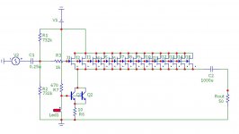
after one night of Jfet matching I found 30 Jfets wirh an Idss from 7.0 to 8.0 ma, so here is the new Schematic:
15x 2SK170 per channel
2x BC550 and one red Led as current source
THD should be in the 0.1X percent range for 1Vrms out
Bias is at ID 5.6ma and Vgs: -75mv.
A fresh piece of Sripboard is ready, have to do some university stuff and will start building the Prototype this night. I dont think a PCB is needed for this project ... but what could we do with 20 BF862 in each channel .... first things first, smd monsters later.
Attachments
otherwise, if you want to have fun without need to read, meet some girls
(modern day women have the use instructions tattooed on the rear, the button 'hit for the next page' doesn't work though, no matter how often you try)
add source resistor for each Jfet
keep dissipation for bjts in sane level
put bleeder on output
bootstrap R1 (divide in two , put cap to gnd)
etc.
PD is 250mw for BC550 they can handle up to 500mw that should be safe
Bleeder was reconmendet earlier just forgot to put in in the schematics
Biggest question: why the source resistors, just gimme a hint or a value so i can start figuring it out myself.
Bootstrapping is a good idea, i will add that.
Thx for the input.
- Status
- This old topic is closed. If you want to reopen this topic, contact a moderator using the "Report Post" button.
- Home
- Amplifiers
- Pass Labs
- A Pass inspired Sk170 Headphone Amp - is this stupid