Hi,
I am running a pair of Aleph4 mono blocks. One question about the optimal bias current through one IRF240/244. Many guys utter that the Aleph2 shall sound better than the Aleph4 – assuming equal build up of PSU etc. The main difference is that in the Aleph2 the power FETs biased to 0,6A each, at Aleph4 just to 0,4A. Has anyone tested it – does the bias point 0,6A sound better?
So why not just reduce the Aleph4 to 4 Fets with 0,6A each? What disadvantages would the loss of dampening cause? Appreciating you comments…
Regards
Klaus
Klaus
When I built my Aleph 1.2's I replaced R19/56K2 (R26/121K in Aleph4 if I'm not wrong) with a 200K trimmer just to see what happens with bias changes.
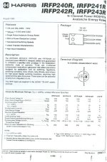
Now, each amp has 10*IRFP242R output mosfets;
when biased @ 330mA each it sounded dry in mids, relatively thin and a bit grainy at the top end, whereas @ 430mA each these phenomena were gone.
Finally I set the bias at 4.5A and the amps sound wonderful.
If your heatsinks are large enough bias the hell out of it and you won't regret it, even if you'll have to change the mosfets in 4-5 years. Just keep a full set of replacement mosfets aside.
Tschuess,
Nickolas")
When I built my Aleph 1.2's I replaced R19/56K2 (R26/121K in Aleph4 if I'm not wrong) with a 200K trimmer just to see what happens with bias changes.
Now, each amp has 10*IRFP242R output mosfets;
when biased @ 330mA each it sounded dry in mids, relatively thin and a bit grainy at the top end, whereas @ 430mA each these phenomena were gone.
Finally I set the bias at 4.5A and the amps sound wonderful.
If your heatsinks are large enough bias the hell out of it and you won't regret it, even if you'll have to change the mosfets in 4-5 years. Just keep a full set of replacement mosfets aside.
Tschuess,
Nickolas


Re: each device has an ideal bias point so...
That's pretty much just how it is. While each device becomes
less linear at a given current, each experiences less signal
current, and you get a cancelling effect.
GringoAudio said:How can the total amplifier bias mean anything? Each device has to be biased so it is operating well within its linear region with no chance of leaving it (Class A) during musical peaks so how is the TOTAL bias meaningful?
That's pretty much just how it is. While each device becomes
less linear at a given current, each experiences less signal
current, and you get a cancelling effect.
So at what point....
...does more bias just become wasteful? I see that unless musical peaks push the current into the outer maxima of the FETs' current handling abilities then you can just increase the bias ad infinitum. With enough devices sharing the load this is unlikely tohappen unless bias is crazy high. How do you decide how many devices to use and how high is high enough for bias? And BTW I will be bragging that Nelson Pass answered my DIYAudio questions alreadys o if anyone else can help me please do so too. Thanks!
...does more bias just become wasteful? I see that unless musical peaks push the current into the outer maxima of the FETs' current handling abilities then you can just increase the bias ad infinitum. With enough devices sharing the load this is unlikely tohappen unless bias is crazy high. How do you decide how many devices to use and how high is high enough for bias? And BTW I will be bragging that Nelson Pass answered my DIYAudio questions alreadys o if anyone else can help me please do so too. Thanks!
Decide how far you want to push each device thermally and go from there. The bias current per device x rail voltage will give you the wattage dissipated for each output device. At that point you simply use enough devices to get your target bias, which you determined beforehand by either looking at the lowest load you intended to drive or how crazy high you wanted to get.
Grey
Grey
cooler...
Thanks for all the answers!
Well, I regret a little bit to have not bought laaaaarger coolers… Now I have somewhat like 30K warm up delta. In summer 60°C at the coolers. I will test the easy R19-tweak and test the sound change to maybe 0,47A per FET, equals +35K.
Regards
Klaus
Thanks for all the answers!
Well, I regret a little bit to have not bought laaaaarger coolers… Now I have somewhat like 30K warm up delta. In summer 60°C at the coolers. I will test the easy R19-tweak and test the sound change to maybe 0,47A per FET, equals +35K.
Regards
Klaus
Re: So at what point....
At some arbitrary point, yes.
GringoAudio said:...does more bias just become wasteful
At some arbitrary point, yes.
I am wondering... would there be a physical explanation for the improvement of the sound quality? Could you estimate "sound" if you had some data of a fet used and its bias setting?
It would surely be interesting to know, it would be an aid to selecting fets and bjts...
Bouke
It would surely be interesting to know, it would be an aid to selecting fets and bjts...
Bouke
I thought there was a limit to how much bias/how many dev in parallel. Besides the SOA there is the input capacity of the mosfet. Too many devices in parallel and the amp will start to sound "dark". NP mentioned something to that effect starting to happen in the biggest aleph.
Aye, but that will vary with the choice of device. Want a heavier, darker sound, perhaps for subwoofers...go for higher Gate capacitance. Or go for less capacitance for a tweeter amp.
I'd place that in the "voicing" category rather than the "heat" category when it came time to make decisions.
Grey
I'd place that in the "voicing" category rather than the "heat" category when it came time to make decisions.
Grey
is there a relationship between number of parallel devices and
rail voltage? Higher voltage spread over more devices is equivalent
to lower voltage over fewer (eg. 2 devices for Aleph 3, 6 for Aleph 2).
Equivalent in that more voltage in more devices overcomes increasing gate capacitence?
(i feel like a 1st grader in Algebra class again!)
rail voltage? Higher voltage spread over more devices is equivalent
to lower voltage over fewer (eg. 2 devices for Aleph 3, 6 for Aleph 2).
Equivalent in that more voltage in more devices overcomes increasing gate capacitence?
(i feel like a 1st grader in Algebra class again!)
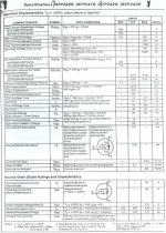
All of the rail voltage is dropped across each fet. you use more fets on larger alephs to decrease current/fet so you don't exceed max wattage per fet. Aleph 2 is .5A at 45V per fet= 22.5Watt. Smaller Alephs have smaller voltage and maybe slightly more current over fewer fets while still not exceeding 25 watts/fet.
I had the bias cranked a little too much and had a fet and source resistor melt down. I think the faital blow was about 4 months ago when I was putting them through the ringers and enjoying too much bias. and they sounded great. I let the sink temp reach 175 deg before I knew it. It seemed to survive, but I bet that weakened the chips bond to the tab and let one of the current source (pos rail) fets short and the active set tried to fight it. I'm hell on fets. 80 volts at 25 amps and 160000 ufs can make a lot of magic smoke very quickly. The 8 source resistors looked like little halogen lights on a dimmer.
I had the bias cranked a little too much and had a fet and source resistor melt down.
I think the faital blow was about 4 months ago when I was putting them through the ringers and enjoying too much bias. and they sounded great. I let the sink temp reach 175 deg before I knew it. It seemed to survive, but I bet that weakened the chips bond to the tab and let one of the current source (pos rail) fets short and the active set tried to fight it. I'm hell on fets. 80 volts at 25 amps and 160000 ufs can make a lot of magic smoke very quickly. The 8 source resistors looked like little halogen lights on a dimmer.Nelson says that it is the total bias and not the bias of each individual mosfet that matters. These may well be true for Vertical Mosfets running in Class A with a relatively high bias current!
One question in this regard is, what if one were using Lateral Mosfets of say, the Hitachi type; these devices require an optimum bias of 100mA. Hence, when parallelling these devices, would one multiply the number of output devices with 100mA or would TOTAL BIAS be set without taking into account the actual current flowing through each mosfet? In the latter case, would these devices still exhibit their negative TC characteristics?
One question in this regard is, what if one were using Lateral Mosfets of say, the Hitachi type; these devices require an optimum bias of 100mA. Hence, when parallelling these devices, would one multiply the number of output devices with 100mA or would TOTAL BIAS be set without taking into account the actual current flowing through each mosfet? In the latter case, would these devices still exhibit their negative TC characteristics?
- Status
- This old topic is closed. If you want to reopen this topic, contact a moderator using the "Report Post" button.
- Home
- Amplifiers
- Pass Labs
- "Sound" of IRF240 bias point setting