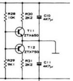
ZM suggested that I start a new thread about powering an AlephJ from a 48VDC source using the Quad virtual ground. I have a few questions that I need to ask before I can get started to be sure I understand the circuit and source the correct parts. For reference, I have attached the pertinent part of the circuit. Questions:
1) Why are the initial two resistors not equal? I would have expected 10k/10k. Now if my math is correct, the midpoint sits at 22.7 which is 1.3 below desired and that happens to be exactly double the Vbe of a bjt. I am sure that is not coincidence, but I can't see how it works.
2) The specified bjts are, of course, obsolete. Can they be replaced with a MOSFET pair? i.e. irf240/irf9240. I assume they would need gate stoppers and that plus the difference in Vgs from Vbe would require a different value for the 9.1k R, but I don't know how to calculate it.
3) I would tend to use larger caps, but given the inherent lack of ripple of a battery supply, maybe that is not needed. How about a 0.1uF bypass?
Thanks for your input. I will be ordering all supplies while I am in US and then building everything when I get back to Panama in a few weeks so this may end up being an intermittent for me. Again, thanks for the help.
Attachments
I thought I posted this previously, but I don't see it, so I'll try again.
Thanks for indulging me. To me, this hobby is part about getting great finished products, but also about understanding how they work.
That is easy enough to do and I am sure I can end up with good results, but I would like to understand how the circuit works and WHY the two resistors are not equal. Can anyone explain it to me? Trial and error is great (and sometimes the only option), but knowledge is better!1. start with equal resistors ; check potential ; alter what's needed
And I assume no heat sink as it is only passing the error current. ?A value like 1k enough? I am not sure what we are aiming for.2.use something in T0220 case ; decrease 2K2 value , to bleed more substantial current
Again looking for understanding. A DC battery should have 0 ripple, so the cap is not "filtering." The only other function I know of for a PS cap is to act as a "reservoir." With AB or B this is certainly necessary, but with Class A operation, I thought it drew the same current all the time. Why, then, would we need a "reservoir?" Again, I am not opposed to using them. The caps are relatively cheap and I have several on hand. I just want to understand what they are doing.3.larger caps , certainly OK ; bypass also OK
Thanks for indulging me. To me, this hobby is part about getting great finished products, but also about understanding how they work.
resistors at bases are voltage dividers ...... and you can take transistors as emiter-followers (buffers) for that voltage level
even simpler - resistors at bases plus transistors are acting as usual bleeders , to help keeping common cap's node at half supply voltage
with 2K2 decrease , current is increased , keeping mid point voltage firmer
even battery supply needs speed ........ and caps are there for that
even simpler - resistors at bases plus transistors are acting as usual bleeders , to help keeping common cap's node at half supply voltage
with 2K2 decrease , current is increased , keeping mid point voltage firmer
even battery supply needs speed ........ and caps are there for that
That much I understood. If they are a voltage divider, why aren't they equal? I am sure it has something to do with the Vgs of the transistors and that using mosfets instead will probably change that, but I do not understand the theory of why they should be different.resistors at bases are voltage dividers ...... and you can take transistors as emiter-followers (buffers) for that voltage level
Understood. How does one determine how much is enough? 1k. 500, 10???with 2K2 decrease , current is increased , keeping mid point voltage firmer
OK, speed. How does a cap provide speed? And what do we mean by speed? I think of speed as rate of change. If the amplifier will be drawing the same amperage all the time, what is changing? I thought Class A amps ran at a steady state and there was not a change in current with changing input/output. Perhaps that assumption is wrong?even battery supply needs speed ........ and caps are there for that
Again, just trying to learn.

...... To me, this hobby is part about getting great finished products, but also about understanding how they work.
cheers to that!
That much I understood. If they are a voltage divider, why aren't they equal? I am sure it has something to do with the Vgs of the transistors and that using mosfets instead will probably change that, but I do not understand the theory of why they should be different.
even your two ears aren't identical , so why expecting N and P counterpart's Vbe needs to be ?

Understood. How does one determine how much is enough? 1k. 500, 10???
more , the merrier , keeping an eye (brain) on resistor and transistor dissipation
say that 20-50mA is overkill
......
OK, speed. How does a cap provide speed? And what do we mean by speed? I think of speed as rate of change. If the amplifier will be drawing the same amperage all the time, what is changing? I thought Class A amps ran at a steady state and there was not a change in current with changing input/output. Perhaps that assumption is wrong?
Again, just trying to learn.
if you look at Universe as big class A amp , and take it in infinitesimal small moment ..... everything is steady
whatever , if you take several of these moments , you'll see that moving to entropy is slow , but certainly one direction oriented process
so - nothing is steady
though , it helps that caps are faster to give than accu

I have applied this version to get a virtual ground in a previous power amp.
I used TO220 bipolars.
Nevertheless I also connected high wattage (5W) resistors between +/-supplies and virtual gnd - just to feel better for safty reasons....
Results were good - system never failed.
And it's a cheap way to get a quasi monaural supply in a stereo amp with a standard tranny which has 2 secondaries
OK, so no theoretical reason for Rs to be different. In fact, theoretically they should be the same. Difference is just an observed fact that compensates for differences between 2 transistors, correct? I wonder why Quad chose the values they did, however. It would seem that it would need to be a case by case situation if you are just correcting for differences in transistor values.even your two ears aren't identical , so why expecting N and P counterpart's Vbe needs to be ?
So 50V/.02A=2500. two R in series (plus 2T) so ~1k each is fine. 50V/2000R=.025A so each R dissipates W=(.025)^2*1000=.625W so 2W resistors needed for safety factor of 3.more , the merrier , keeping an eye (brain) on resistor and transistor dissipation
say that 20-50mA is overkill
Too metaphysical for me. How do caps help 'speed' other than being a reservoir for instantaneous demand? If a Class A amp draws a continuous 100W (for example), other than the ramp up (where an RC network helps avoid in rush current by making it 'slow'), even looking at each 'instant' there is 100W into cap and 100W out of cap. Does it have to do with the 'impedance' of the PS? I have seen this discussed, but don't really understand it.if you look at Universe as big class A amp , and take it in infinitesimal small moment ..... everything is steady
whatever , if you take several of these moments , you'll see that moving to entropy is slow , but certainly one direction oriented process
so - nothing is steady
though , it helps that caps are faster to give than accu
It' s a must to connect some speed-up caps parallel to a battery. Batteries behave like big and slow caps; they can storage energy - but nothing else. It's similar if you use cheap/high ESR or expensive/low ESR caps in your design.
Personally I go a step further with connecting small caps close to drains/collectors of each power device, not only to improve ESR but also to compensate inductive components of wiring.
Personally I go a step further with connecting small caps close to drains/collectors of each power device, not only to improve ESR but also to compensate inductive components of wiring.
In reply to the question of why the resistors are not of equal value, Quad chose to use different supply voltages, in the 606 they are +57.8V and -53.4V which are with in 1% of what you would expect using 10K and 9K1 resistors, Why Quad chose asymetric supply voltages is an other question
Stuart
Stuart
Question Solved!
Thanks for setting this straight!
So much for all the quandary of why the resistors were different.In reply to the question of why the resistors are not of equal value, Quad chose to use different supply voltages, in the 606 they are +57.8V and -53.4V which are with in 1% of what you would expect using 10K and 9K1 resistors, Why Quad chose asymetric supply voltages is an other question
Stuart
Thanks for setting this straight!Another option?
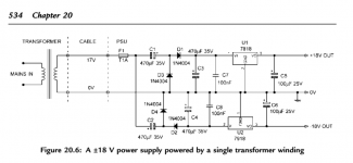
I stumbled across the attached schematic with no explanation or text attached. I am trying to understand it. Is it like two voltage doublers connected to the same winding in reverse directions? What about the medium sized caps BEFORE the diodes as well as AFTER them? It appears that the bipolar output (+18, 0, -18) is, indeed a bit more than double the input (+17, 0). I assume that with different tranny and different voltage regulator you could achieve most any voltage you want. It would also appear to need a lot more capacitance - ?applied after the circuit show? ?Replace the 100uF with 1000 or 10,000?
I think I will go with Papa's elegantly simple solution, but I sure would appreciate any help trying to understand how this circuit works. After all, half the point of this hobby is LEARNING as we go!
Attachments
Actually for this project, I don't have a transformer. I plan to run it off a 48VDC battery bank (the primary bank for my solar house). It was just that in rummaging through old files on bipolar supplies, I came across this and was trying to understand how (?if?) it worked.dmtparker - What is the exact transformer you have?
But your 48V battery bank is made from (4) 12V batteries in series... You could make a virtual ground in-between the two center batteries and you're done. Ground is relative.
Do you really want a Class-A amplifier (read as 'incredibly inefficient') running in a solar house?
Do you really want a Class-A amplifier (read as 'incredibly inefficient') running in a solar house?
- Status
- This old topic is closed. If you want to reopen this topic, contact a moderator using the "Report Post" button.
- Home
- Amplifiers
- Pass Labs
- Quad type bipolar PS for AlephJ