small revelation
I looked at the attached schematic by lhquam [post#69] and this new thought came to mind from an older one which he proposed earlier.
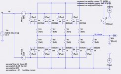
1. View this amp as a diyF4, and an SE amp operating in parallel for the sake of discussion.
2. DiyF4 is maybe 5 times more powerful than SE based on the relative number of P-Mosfets therein each.
3. Mentally disable SE amp.
4. Load diyF4 with 8 Ohms and push through it 1 Amp peak to peak as an example.
5. Add SE amp and ask:"what is the apparent load to it; is it 8 ohms, or is it 40 Ohms or higher? I think the answer is not 8 Ohms but way higher.
6. DiyF4 and SE amps share the same Vout [8 Vp-p in this example] to the load. It follows that the current contribution of SE in the total current output is calculated to be 8 Vp-p divided by 40 Ohms[for example]or equal to 0.2 A p-p.
7. Since the SE amp idles at 0.3 A peak [ per lhquam, and for example from my prototype], its P-Mosfet stays in conduction throughout the cycle.
8. It follows that in the balanced mode of operation, the resultant bridged anti-phase SE amp [in the consolidated amp] also stays active [linear], and further enriches the overall output with 2nd order harmonics per an earlier post by Mr. Pass.
The apparent load to SE amp of >> 8 Ohms [in example] reminds me of current bootstrapping in the STASIS power output stage.
I looked at the attached schematic by lhquam [post#69] and this new thought came to mind from an older one which he proposed earlier.
1. View this amp as a diyF4, and an SE amp operating in parallel for the sake of discussion.
2. DiyF4 is maybe 5 times more powerful than SE based on the relative number of P-Mosfets therein each.
3. Mentally disable SE amp.
4. Load diyF4 with 8 Ohms and push through it 1 Amp peak to peak as an example.
5. Add SE amp and ask:"what is the apparent load to it; is it 8 ohms, or is it 40 Ohms or higher? I think the answer is not 8 Ohms but way higher.
6. DiyF4 and SE amps share the same Vout [8 Vp-p in this example] to the load. It follows that the current contribution of SE in the total current output is calculated to be 8 Vp-p divided by 40 Ohms[for example]or equal to 0.2 A p-p.
7. Since the SE amp idles at 0.3 A peak [ per lhquam, and for example from my prototype], its P-Mosfet stays in conduction throughout the cycle.
8. It follows that in the balanced mode of operation, the resultant bridged anti-phase SE amp [in the consolidated amp] also stays active [linear], and further enriches the overall output with 2nd order harmonics per an earlier post by Mr. Pass.
The apparent load to SE amp of >> 8 Ohms [in example] reminds me of current bootstrapping in the STASIS power output stage.
Attachments
... reminds me of current bootstrapping in the STASIS power output stage.
I'm not certain that no one ever used the phrase current bootstrap before
me, but I have not seen it.


I'm not certain that no one ever used the phrase current bootstrap before
me, but I have not seen it.
My apology for the incorrect use of current bootstrap in the context of STASIS.
Subjective assessment
1. Absent negative feedback [see post#187 for schematics], the prototype performed exactly like it did with Option 2 [data in the parent post].
2. Music [using one Polk Monitor 4B; post#144] was more pleasing, clear, relaxed, detailed and sparkling with Option 1 [no negative feedback] than with Option 2.
3. This prototype was dead silent; no hum, hiss etc with my right ear at the drivers.
4. The "bridged anti-phase single ended amp circuit of lhquam is highly recommended/worthy of DIY assembly, and scale-up to a high power output capability.
Best regards.
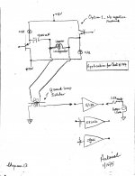
The above objective and listening evaluations were done.I will repeat this current test by using Option 1 [capacitor-coupled load] which will not use negative feedback from the power outputs [Va and Vb] to the Op Amp inverting inputs. It follows that I will have two options to listen to its performance in bridged anti-phase SE mode; with and without negative feedback.
1. Absent negative feedback [see post#187 for schematics], the prototype performed exactly like it did with Option 2 [data in the parent post].
2. Music [using one Polk Monitor 4B; post#144] was more pleasing, clear, relaxed, detailed and sparkling with Option 1 [no negative feedback] than with Option 2.
3. This prototype was dead silent; no hum, hiss etc with my right ear at the drivers.
4. The "bridged anti-phase single ended amp circuit of lhquam is highly recommended/worthy of DIY assembly, and scale-up to a high power output capability.
Best regards.
Please post the thoughts which you feared will disgrace you. I am confident you will not shoot yourself in the foot. Speak up clearly; hopefully like I do..
(Mighty Moi erased 3 lines of comment , avoiding another public disgrace)
Last edited:
Application for Post#144
The prototype was used as a combination power amp and preamp as depicted in the attached schematic.
1.The prototype powered the upper Polk loudspeaker of the mirror image pair in post#144.
2. Its voltage output was ground-loop isolated, and became the input signal to either a Threshold S/150, a Kenwood KR6050 receiver, or a Class T amplifier [MCM].
3.The high power amps drove the bottom Polk loudspeaker of the pair in phase with the upper. Both loudspeakers can also be operated out of phase with some loss in bass. I used a 2.5A fast fuse in line with this loudspeaker.
This is a first for me to qualify the resultant sound as awesome; especially with S/150. I was also surprised with the excellent performance due to Kenwood and Class T amps; provided their power output was increased [with their built in vol controls] to be in the power range like S/150.
Best regards
Attachments
In the Pass Labs XA.8 Owners Manual https://passlabs.com/images/uploads/manual/Point_8_OM_web.pdf there is this statement:
The second element is the higher level of single-ended Class A bias current applied to the output stage, allowing arbitrary control of the values and ratios of the second and third harmonic characteristic.
Does anyone know whether the control of values of h2 and h3 must be done at design or assembly time, or can such adjustments be made to the assembled product? I can understand the former, but not the later.
My apology for the incorrect use of current bootstrap in the context of STASIS.
I think it's correct, I was merely taking credit for originating it.
Current bootstrap is in the Abstract of your patent US 4,107,619; granted Aug. 15, 1978, and appears 2 additional times in its body.I think it's correct, I was merely taking credit for originating it.
Best regards
As lhquam and I have reported here we had big problems to get second harmonic distortions in a bridged amplifier. Now I found the reason. The discription is a little bit too long for a posting so I put into a pdf file.
Attachments
As lhquam and I have reported here we had big problems to get second harmonic distortions in a bridged amplifier. Now I found the reason. The discription is a little bit too long for a posting so I put into a pdf file.
I have been working on this problem and think I am very close to the solution. As a clue, carefully read the Xs Users Manual paragraph about Cascode Local Feedback. https://passlabs.com/images/uploads/manual/Xs_amp_om.pdf
As lhquam and I have reported here we had big problems to get second harmonic distortions in a bridged amplifier. Now I found the reason. The discription is a little bit too long for a posting so I put into a pdf file.
Hello pr.The first schematic [pdf] is interesting. What is its harmonic profile without the balanced push-pull stages [if possible]; just the balanced SE?
Best regards
Hello lhquam. Beginning the last paragraph of page 6; does need careful reading, and understanding. Please show a schematic of this Pass innovation named Cascode Local Feedback.I have been working on this problem and think I am very close to the solution. As a clue, carefully read the Xs Users Manual paragraph about Cascode Local Feedback. https://passlabs.com/images/uploads/manual/Xs_amp_om.pdf
Best regards
Hello pr.The first schematic [pdf] is interesting. What is its harmonic profile without the balanced push-pull stages [if possible]; just the balanced SE?
Best regards
Believe me, it is far more interesting and enlighting when you find it out yourself.
Here is a link to helpful information about the simulation program, it is free and works great:
http://www.diyaudio.com/forums/software-tools/260627-installing-using-ltspice-beginner-advanced.html
The .asc-files in my last post are the simulation files as schematics. Simply load them into LTSpice and do the simulation and change the circuitry as you like.
As lhquam and I have reported here we had big problems to get second harmonic distortions in a bridged amplifier. Now I found the reason. The discription is a little bit too long for a posting so I put into a pdf file.
Very interesting!
The post of Nelson seems to say that you should do as much k2 in the outputstage and as less as possible in the input stage.
The interaction really seems to be complicated and I suppose the .8 are real masterpieces in organizing the wanted distortion.
http://www.diyaudio.com/forums/pass-labs/264094-xa-8-single-ended-current-sources-3.html#post4107420
Believe me, it is far more interesting and enlighting when you find it out yourself.
Here is a link to helpful information about the simulation program, it is free and works great:
http://www.diyaudio.com/forums/software-tools/260627-installing-using-ltspice-beginner-advanced.html
The .asc-files in my last post are the simulation files as schematics. Simply load them into LTSpice and do the simulation and change the circuitry as you like.
Thank you for your reply and recommendation to visit the thread initiated by Mooly which shows a systematic study "syllabus" of this science.
Hello lhquam. Beginning the last paragraph of page 6; does need careful reading, and understanding. Please show a schematic of this Pass innovation named Cascode Local Feedback.
Best regards
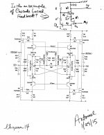
Hello lhquam. I did not find a circuit which is an example of Cascode Local Feedback [CLF]. So I used its descriptive words [CLF] to write a schematic which maybe or not the desired subject.
The image shows your artwork from post #94. In the top right corner is this possible CLF schematic; with focus on Q8 and Q4 below it as an example. The joint emitter of Q8 and the drain of Q4 is a summing junction where the two out of phase signals combine.
Best regards.
Attachments
- Status
- This old topic is closed. If you want to reopen this topic, contact a moderator using the "Report Post" button.
- Home
- Amplifiers
- Pass Labs
- XA.8 single-ended current sources