Hello there,
I just got an idea to do an unusual thing:
I love my F2Js, they are awesome. They are, however, not as awesome when used closed to driver fs where they generate way more distortion than a voltage amp up to about 300 hz on those specific drifers ( fs ~ 75 hz ). I do have a voltage amp close by, my idea is to parallel both amplifiers but with an active crossover such that the voltage amp handles below 300 hz and the F2j above.
You might ask why I don't just add another driver? I can do that but my goal is is a light and small speaker and another driver counters both of those =)
And then a practical question about the series resistors: Do I need to add a resistor to the voltage amp such that the F2J doesn't fight it? But the F2J already has high output impedance so I don't need to add anything to it... or?
Last edited:
Antoinel made some investigations in that , combining voltage and curent amps
Hello Zen Mod. You have a great memory. Some of the schematics I suggested of combo amps are in the F6 thread. I'll need to study OllBoll's note, and reply.
Best regards
when you parallel a Current source output with a Voltage Source output you get a Voltage Source output
at best the Current Source amplitude and phase matches the load and "unloads" the Voltage Source output Q
but the Vsource low output Z dominates, ideally is unchanged by the paralleled Isource amp
frequency shaping the output Z of an amp, tweaking for a particular load is possible - but it really is a advanced EQ problem which could be done with mixed positive/negative frequency shaping feedback
or use power passive EQ parts
simply paralleling Isource, Vsource amp outputs won't do it
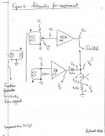
Hello OllBoll. I searched F6 Thread and found my mention of Compound Power Amplifiers in post # 886. I then searched the Pass Labs Forum for Compound Power Amplifiers and located my thread dating back to 14th August 2012. The attached diagram was the outcome to understand the output stage of F6.
1. The transformer was a voltage step down power toroid [120 Vac:12 Vac] I used to simulate the Jensen transformer in F6. Note the phase of the windings which I used [bottom secondary] to invert the output phase of the amp labelled TCA
2. VSA [non-inverting] was THRESHOLD S/150 voltage source amp to simulate the upper JFET of F6; I thought operated in common drain configuration.
3. TCA [inverting] was a diy current source amp [trans conductance] which simulated the bottom JFET in F6; I thought operated in common source configuration.
3. The resistors [0.5 Ohm] were used to sense the current contribution of each power amp by using a voltmeter in AC mode.
4. To start, both power amps were turned on; but with the switch off at VSA's output Eo. An input signal Vi [30-150 Hz] was applied and scanned to TCA to get Vo'. This allowed me to graph the impedance curve of the woofer in loudspeaker [Vo' versus Freq]. The minimum value of woofer impedance was at ~100 Hz.
5. Vi was then set at 100 Hz. and the vol control [25 Ohm] at input of S/150 dialed to make Eo equal to Vo'. Switch at output of Eo and Vo' was then closed.
6. The frequency [30-150 Hz] was scanned again to find that the characteristic impedance curve of woofer had disappeared; in favor of an output Eo or Vo which was almost invariant with frequency.
7. S/150 "absorbed" excess Vo' [from TCA current = constant multiplied by rising impedance] as it emerged . But the output impedance at Eo or Vo [switch closed] was that of S/150 reported at 300 milliOhms. This meant an excellent damping of woofer.
8. This parallel compounding treated the loudspeaker's total frequency range.
What is the voltage source amp [and simple] schematic which you have? The schematic of F2J is available at FIRST WATT
I hope this helps.
Best regards.
Attachments
I do have a voltage amp close by, my idea is to parallel both amplifiers but with an active crossover such that the voltage amp handles below 300 hz and the F2j above. And then a practical question about the series resistors: Do I need to add a resistor to the voltage amp such that the F2J doesn't fight it? But the F2J already has high output impedance so I don't need to add anything to it... or?
You can parallel two current source amps into a common load, but not a voltage source amp with a current source amp.
Adding a resistor to the voltage source amp makes it more of a current source. You will need to adjust the relative amp
input levels to match the two output levels, due to the differing output impedances.
The voltage amp would be a Hypex Ucd Class D amp and the current an F2J-ish amp ( CS exchanged for a big inductor for moar efficiency ") )
)
Level matchings and such wouldn't be a problem, I have 2 separate active channels I can with DSP fix to whatever I want. The big question is just will it work, or will there be major issues?
After testing some more it looks more likely that I'll just add another driver for the voltage amp and not try to dual-amp my dual 6" mids. They didn't perform well enough in the 100-300 hz region even with a voltage amp ( although far less bad than a current source of course ) so I'm probably going to chuck in my 10" I have lying around so I won't compromise performance.
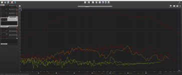
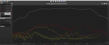
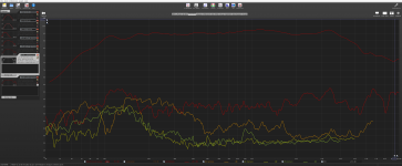
For the comparison I'll just throw up the distortion measurements: Note that I was lazy so I didn't correct low frequency response so take the measurements below 200 hz with a grain of salt.
The drivers are 2 series connected 6ND430 where one is physically inverted for some 2nd distortion reduction. The voltage source is a Class AB I had lying around close and the current source is the inducted F2J, the 1 damping factor is the F2J but with 16 ohm in parallel.
The driver doesn't have a shorting cap, it has very low distortion but with a current source it gets stupid low distortion at 500 hz and upwards =)
)Level matchings and such wouldn't be a problem, I have 2 separate active channels I can with DSP fix to whatever I want. The big question is just will it work, or will there be major issues?
After testing some more it looks more likely that I'll just add another driver for the voltage amp and not try to dual-amp my dual 6" mids. They didn't perform well enough in the 100-300 hz region even with a voltage amp ( although far less bad than a current source of course ) so I'm probably going to chuck in my 10" I have lying around so I won't compromise performance.
For the comparison I'll just throw up the distortion measurements: Note that I was lazy so I didn't correct low frequency response so take the measurements below 200 hz with a grain of salt.
The drivers are 2 series connected 6ND430 where one is physically inverted for some 2nd distortion reduction. The voltage source is a Class AB I had lying around close and the current source is the inducted F2J, the 1 damping factor is the F2J but with 16 ohm in parallel.
The driver doesn't have a shorting cap, it has very low distortion but with a current source it gets stupid low distortion at 500 hz and upwards =)
Attachments
Last edited:
The voltage amp would be a Hypex Ucd Class D amp and the current an F2J-ish amp ( CS exchanged for a big inductor for moar efficiency
Yes, it should work, just use a large enough power resistor for the voltage amp.
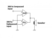
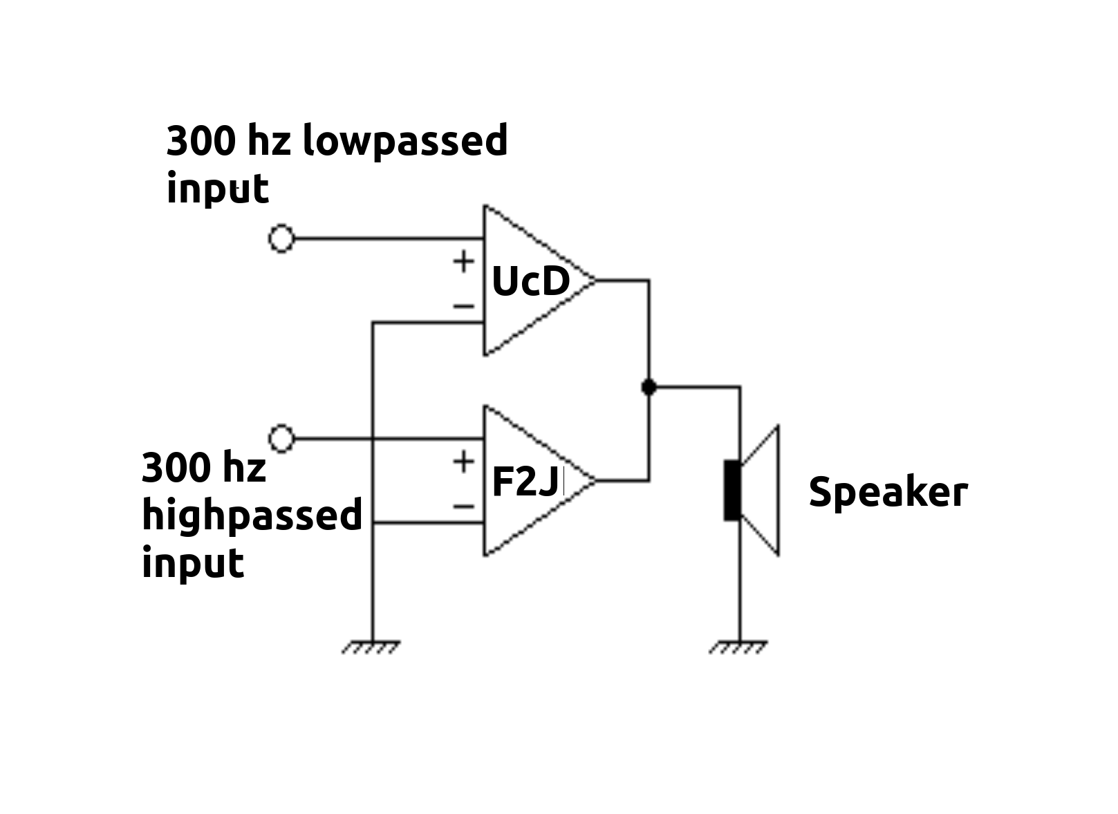
The idea would be to do this:
Each amp is driven form it's own DAC with its own DSP. If each amp had its own speaker it would work no problem, but the question is if we could let both amps drive the same speaker while keeping the output impedance characteristics of the amps. So in essence the speaker is voltage driven below 300 hz and current driven above. So ideally the output impedance that the speaker sees should be = [Speaker impedance] at 300 hz, increase 4x per octave above 300 hz and be reduced to 1/4 per octave below 300 hz.
Or will it just be driven as a handicapped combination of both voltage and current source over the operating range?
Attachments
The idea would be to do this:
Each amp is driven form it's own DAC with its own DSP. If each amp had its own speaker it would work no problem, but the question is if we could let both amps drive the same speaker while keeping the output impedance characteristics of the amps. So in essence the speaker is voltage driven below 300 hz and current driven above. So ideally the output impedance that the speaker sees should be = [Speaker impedance] at 300 hz, increase 4x per octave above 300 hz and be reduced to 1/4 per octave below 300 hz.
Or will it just be driven as a handicapped combination of both voltage and current source over the operating range?
OllBoll. Please play this game.
1. Apply 100 Hz to UCD only as an example of lowpass. UCD's output goes directly to loudspeaker, and to the three 47 Ohms in parallel which define Zo [47 divide by 3 ~15 Ohms] for your diyF2J. Disable them for the time being so they do not siphon power from UCD. Thus, UCD output power goes only to loudspeaker; to damp the woofer etc..
2. Apply 1KHz to diyF2J only as an example of high pass. The output port of UCD is at ~zero impedance, and gobbles up exclusively diyF2J's output signal; meaning nothing shows up at loudspeaker.
3. But; apply all pass to UCD, and high pass only to diyF2J; such that the signal levels of UCD and diyF2J in the high pass region are equal in amplitude and be in-phase. The loudspeaker in the low pass region receives exclusive power from UCD. The loudspeaker in the high pass region receives equal power contributions from UCD and diyF2J. Output impedance at loudspeaker defaults to or is that of UCD over the audio spectrum..
4. You may choose in the hi pass region to have the output voltage of UCD at a higher [but not lower] value than that of diyF2J; which will gve a different power contribution ratio in loudspeaker.
What do you think?
Hi,
That won't work either, even with the same signal the UCD
supplies all the power to the load, all your cancelling is the
current in the F2J, and If you increase UCD voltage over
F2J, UCD simply starts driving the F2J as well. Highpassing
the F2J simply means the UCD will drive it a low frequencies.
Your not getting anywhere fast, or achieving the desired
result, low impedance at low frequencies, high at high.
Variable Amplifier Impedance
Stick a cap or so in there and you should be able to do it, an
amplifier than varies from low impedance at low frequencies
to high impedance at high frequencies smoothly transferring
the current delivery from the top amp to the bottom amp.
rgds, sreten.
Makes sense.
I did try to add inductors parallel to the F2J-ish amp but to get as close to a voltage source as I would need I would waste too much power. I think I know the "best" solution though if I wanted to do it:
Cut back on the source resistors to increase gain, add voltage feedback below 300 hz and add current feedback above.
It would make the amp significantly more complicated though =)
did you read this http://firstwatt.com/pdf/art_cs_amps.pdf
Of course, a long time ago.
- Status
- This old topic is closed. If you want to reopen this topic, contact a moderator using the "Report Post" button.
- Home
- Amplifiers
- Pass Labs
- Parallelling voltage + current source amp with active crossove?