Yes, you have it right.No, its not the RF bleeding through the power supply that AndrewT is talking about its the RF that is radiated by the plates that can interfere with the amplifier.
Every loop in a circuit is potentially an aerial.
It radiates and/or receives EMI.
The plates, due to the very high current pulses passing around the loop, will be radiating those pulses as EMI INSIDE your amplifier.
low levels or high levels of interference mixed with the signal at the output.
Those with a good measurement system will be able to see the spikes above the noise floor.
There are some nice examples here on the Forum.
Some show lots of mains harmonics stretching all the way up to the test frequency and beyond. The 19th is 950Hz. Others have these spikes buried in the noise floor.
Great discussion. Although I am not insistent only inquisitive. If the plates emit or receive RF that the rest of the amplifier could pick up and negatively affect the sound, then Pass Labs, darTZeel (NHB-108), and other manufacturers must have found a solution to negate the effect. Any ideas how?
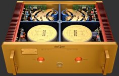
Here is a pic of the NHB-108, maybe the curve in the plates change the effect? This amp series runs $30,000 to $50,000, FYI.
Twisted pairs is always a safe method. However, depending on the components being connected, twisting also effects the outcome. Could be a positive or negative effect. Twisted pairs can roll off high frequencies. Wilson uses this to advantage on one of their speakers. They use a tightly twisted pair from the crossover to the tweeter to purposely roll of some of the high frequency and at the same time eliminate a resistor by the longer amount of wire shortened by the twisting, as an example.
Here is a pic of the NHB-108, maybe the curve in the plates change the effect? This amp series runs $30,000 to $50,000, FYI.

Twisted pairs is always a safe method. However, depending on the components being connected, twisting also effects the outcome. Could be a positive or negative effect. Twisted pairs can roll off high frequencies. Wilson uses this to advantage on one of their speakers. They use a tightly twisted pair from the crossover to the tweeter to purposely roll of some of the high frequency and at the same time eliminate a resistor by the longer amount of wire shortened by the twisting, as an example.
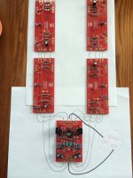
Thanks for the confirmation! And thanks to whoever designed the boards. By centering the FE board on the back panel and N and P boards on each side, make for very short connections for input, speaker, and filtered DC supply.That's perfect.
I'm just about done stuffing all the boards and getting ready to start screwing them in place and start the wiring. I'm confused about the location to tie in the speaker (-) & (+), as I've seen a couple conflicting pictures. Please review and let me know if I have it right
View attachment 446175
Have you considered the size of the wire you will be using for these connections?
Nash
I have a few PCB smoothing banks, very few.
I mostly use hard wired capacitors for smoothing the rectified DC.
I run a twisted pair from transformer to rectifier.
I run a twisted pair from rectifier to capacitor1.
I run a twisted pair from capacitor1 to capacitor2.
I run a twisted pair from capacitor2 to amplifier.
At every termination I try to minimise Loop Area.
I find this gives so little radiated interference that I can pass an unscreened interconnect anywhere around the PSU and the transformer, that I cannot measure (on a 200.0mVac DMM) any increase or change in output noise from the amplifier.
In my (somewhat blinkered) view a twisted pair hard wired PSU performs better than any pcb or plate version of the capacitor bank.
I am an absolute believer in twisted pairs.
I am with you on the twisted pairs. In the amp being built in this thread would you twist the gate and output wires together from the FE board to the output boards? The other connections are + and G or - and G depending on the output board and those should be twisted. Just not sure about the gate and output wires.
I note you have used the word "hardwired". Any specific reason for soldering all PSU connections as opposed to using those nifty screw on terminals?
Thanks.
Nash
Yes. Between each of the N and P boards I have 16ga Neotech-71448 solid core UP-OCC copper, Teflon jacket. 16ga just fits the holes in the board.Have you considered the size of the wire you will be using for these connections?
Nash
From FE boards to to the P and N boards I have Cardas-52931 15.5 awg copper stranded Litz.
I will have to get creative to connect to boards, will not fit openings. I like the way ZenMod used a smaller ga solid wire, looped around the end of the wire, and then soldered then solid wire and loop together at the opening in the board.
I don't know. The question also applies to every remote mounted transistor, the gate/base current is completely swamped by the current in the collector/drain to emitter /source loop. There is potential for interference and I have not sorted that in my head. Yet the base/gate current is sourcing current that must return in one or other of the high current connections. It seems the gate/base wire/trace should be close coupled. But that frightens me - oscillation !....................In the amp being built in this thread would you twist the gate and output wires together from the FE board to the output boards? The other connections are + and G or - and G depending on the output board and those should be twisted. Just not sure about the gate and output wires.
Are you referring to screw terminal smoothing capacitors?I note you have used the word "hardwired". Any specific reason for soldering all PSU connections as opposed to using those nifty screw on terminals?
I don't use them, too expensive.
I use snap in leads and solder as close to the cap casing/bung as I can.
!Are you referring to screw terminal smoothing capacitors? I don't use them said:Sorry my question was not clearly worded. You mention twisted wires from transformer secondaries to rectifier. If using the monolithic rectifiers do you solder (hardwire) directly to the tabs or use Faston type connectors? If using a rectifier board do you solder (hardwire) the secondary wires directly to the rectifier board or use a screw terminal block on the rectifier board and connect the wires that way?
Thanks. Nash
Yes. Between each of the N and P boards I have 16ga Neotech-71448 solid core UP-OCC copper, Teflon jacket. 16ga just fits the holes in the board.
From FE boards to to the P and N boards I have Cardas-52931 15.5 awg copper stranded Litz.
I will have to get creative to connect to boards, will not fit openings. I like the way ZenMod used a smaller ga solid wire, looped around the end of the wire, and then soldered then solid wire and loop together at the opening in the board.
So gate and output to speaker binding posts would also be the Cardas 15.5?
I don't know but shouldn't the wire to the gate be of smaller cross section? I realize I am thinking this out too much but want to learn the whys rather than just doing it. If you look at the boards carefully you will see that the traces for the gates are smaller than the traces for the +,_,G and outputs.
Nash
Completed the assembly of the first "P" channel side. Takes a lot of time making all the extensions. Each device is 2" up from the bottom of its sink.
Instead of washers I took Dazed2 advice and used a small heatsink. Cheap and can't hurt.
The Mur3020's are on top, J201's on the bottom
See anything wrong so far?
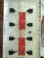
Instead of washers I took Dazed2 advice and used a small heatsink. Cheap and can't hurt.
The Mur3020's are on top, J201's on the bottom
See anything wrong so far?

As I'm completing attaching the N and P boards to the heatsinks I thought it a good idea to go ahead and solder in the leads going to the FE board. As has been discussed, the openings in the boards for the leads are on the small side.
I'm using 15.5 ga Cardas litz wire running between the N and P boards and the FE board. The holes in the boards will only fit 22-20 ga stranded.
I had planned on wrapping the end with a smaller solid wire through the opening, like I saw ZenMod do. That works good when you want the wire coming off the board at a 90*, but I decided I need to come straight out.
So I stripped the insulation off about 3/8" up, then using the 20 ga notch on the stripper I cut the strands off about 3/16" up.
Each strand of the Litz wire is insulated so you have to flux/solder/clean the insulation off and make sure the ends are well tinned before inserting into the boards.
I filled the solder pads on both sides of the boards and then re-insulated with shrink wrap.
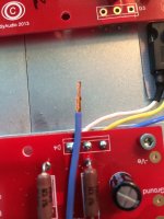
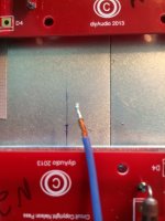
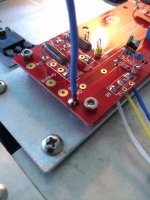
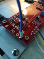


I can't believe how long it takes me to assemble. It took me about 8 hours this weekend to mount the N and P boards to the heatsinks, wire in the extensions to the devices on the heatsinks, and solder in the leads to the FE boards. (1 amp only). Second will go a little faster.
But anyway, here is a couple pics.
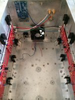
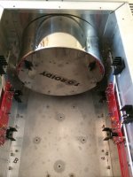
But anyway, here is a couple pics.


- Status
- This old topic is closed. If you want to reopen this topic, contact a moderator using the "Report Post" button.
- Home
- Amplifiers
- Pass Labs
- Aloha F5 v3 Monoblock build
